
SPIDER Automation Dual Monster Moto VNH3ASP30 Motor Driver Shield | 2-Channel 14A High-Current Driver | For 12–16V DC Motors
Description
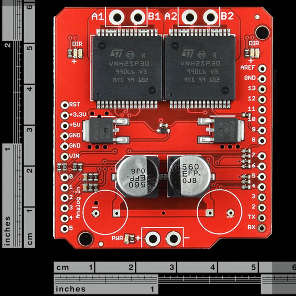
The SPIDER Automation Dual Monster Moto Shield VNH3ASP30 is a high-current, dual-channel DC motor driver shield designed for applications that require reliable control of two high-power brushed DC motors. The board uses a pair of VNH3ASP30 full-bridge motor driver devices, providing significantly higher current-handling capability than conventional low-current motor driver shields.
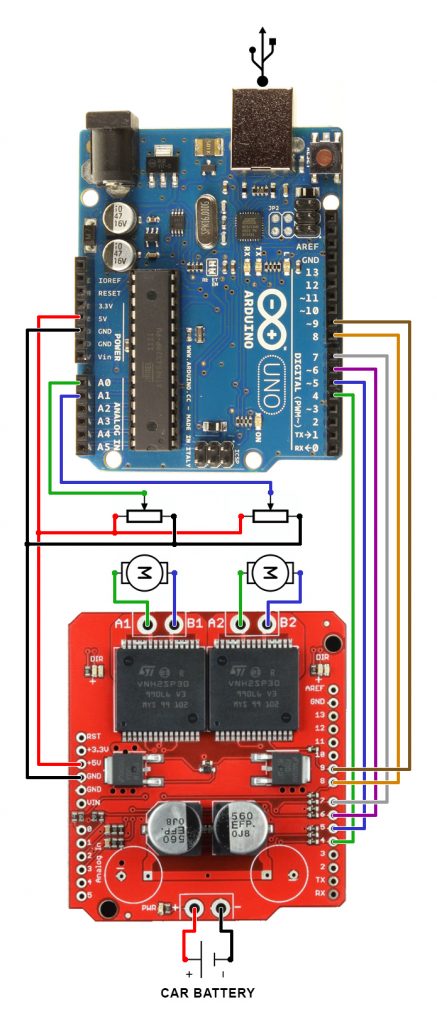
Each motor channel provides dedicated INA and INB direction-control inputs along with a PWM control input for motor activation and speed control. This makes the shield suitable for embedded motor-control systems where forward/reverse direction, PWM speed control and current monitoring are required from a microcontroller such as an Arduino-compatible controller.
The power and motor-output connections are designed with a 5mm terminal pitch, providing a practical interface for larger-gauge motor wiring. Screw terminals are not included with the board and can be installed separately according to the wiring requirements of the application.
The VNH3ASP30 devices also provide integrated protection functions including thermal shutdown, undervoltage shutdown and overvoltage shutdown. Current-sense outputs are available for monitoring motor load through an analog input, with an approximate current-sense output of 0.13V per ampere.
The shield is intended for demanding motor-control applications such as mobile robotic platforms, high-current actuator systems, motorized mechanisms and embedded vehicle-style drive systems. For high-load operation, appropriate thermal management and wiring practices should be used according to the actual motor current and duty cycle.
Key Features
- Dual Motor Driver: Provides independent control of two brushed DC motors from a single shield.
- VNH3ASP30 Full-Bridge Drivers: Uses two VNH3ASP30 high-current full-bridge motor driver devices.
- 14A Per Motor Channel: Designed for motor loads up to the specified 14A channel rating.
- 30A Peak Capability: Supports high-current peak loads according to the supplied product specification.
- 12–16V DC Operation: Suitable for motor systems operating within the specified supply-voltage range.
- Independent Direction Control: INA and INB inputs provide directional control for each motor channel.
- PWM Motor Control: PWM inputs provide electronic motor enable and speed-control capability.
- 20kHz PWM Support: Supports a maximum PWM frequency of 20kHz.
- Analog Current Sensing: Current-sense output can be connected to an Arduino analog input for motor-current monitoring.
- 0.13V/A Current-Sense Output: Provides approximately 0.13V of sense output for each ampere of output current.
- Low MOSFET Resistance: MOSFET on-resistance is specified at approximately 19mΩ per leg.
- Thermal Shutdown: Integrated thermal protection helps protect the driver under excessive-temperature conditions.
- Undervoltage Protection: Provides shutdown protection during undervoltage conditions.
- Overvoltage Protection: Provides shutdown protection during overvoltage conditions.
- 5mm Terminal Pitch: VIN and motor-output connections are arranged for 5mm-pitch screw-terminal connections.
- Large-Gauge Wiring Support: The power and motor-output arrangement facilitates connection of larger motor wires.
- Arduino-Compatible Control Interface: Control signals can be interfaced with Arduino-based embedded control systems.
Benefits
- High-Current Motor Control: Provides a practical solution for applications requiring substantially higher motor current than basic motor-driver modules.
- Two Motors from One Board: Reduces the need for separate motor-driver boards when independently controlling two DC motors.
- Precise Motor Control: Separate direction and PWM inputs provide flexible control of motor direction and speed.
- Current Feedback: Analog current sensing allows the controller to monitor motor load and implement application-specific protection or control logic.
- Integrated Protection: Thermal, undervoltage and overvoltage shutdown functions provide additional protection for the driver electronics.
- Flexible Wiring: The 5mm terminal arrangement is suitable for larger-gauge motor and supply wiring.
- Embedded-System Integration: Control and sensing interfaces make the shield suitable for microcontroller-based motor-control architectures.
Motor Control Interface
- INA: Direction-control input for the corresponding motor channel.
- INB: Direction-control input for the corresponding motor channel.
- PWM: Motor enable and speed-control input through pulse-width modulation.
- CS: Current-sense output providing an analog signal proportional to motor output current.
Current Sensing
The VNH3ASP30 driver provides a dedicated CS current-sense output that can be connected to an analog input of an Arduino-compatible controller. The supplied specification indicates an approximate output of 0.13V per ampere of motor output current. This feedback can be used for motor-load monitoring, current limiting strategies and system diagnostics.
Applications
- Mobile Robotic Platforms: Dual-motor drive systems requiring higher-current motor control.
- Industrial Motor Mechanisms: Embedded control of high-current brushed DC motors.
- Motorized Actuators: Direction and PWM control of DC motor-driven mechanical systems.
- Arduino Motor-Control Systems: High-current motor interfaces for Arduino-compatible embedded controllers.
- Autonomous Platforms: Two-channel motor drive architectures requiring current feedback.
- Vehicle-Style Drive Systems: Independent forward/reverse and PWM control of two DC motors.
- High-Power Embedded Prototypes: Development and testing of higher-current DC motor-control systems.
Thermal & High-Current Installation Considerations
For high-demand motor applications, thermal performance depends on motor current, duty cycle, ambient conditions and the overall mechanical and electrical system. Additional thermal management such as a heat sink or cooling fan may be required for demanding operating conditions.
For higher-current installations, appropriate high-current wiring and secure electrical connections should be used. The supplied product information also notes that direct soldered wiring may be preferable to screw-terminal connections in certain extreme high-current applications.
Package Includes
- 1 × Dual Monster Moto Shield VNH3ASP30 DC Motor Driver
- Accessory as shown in the product image
Technical Specifications
| Parameter | Specification |
|---|---|
| Product Type | Dual DC Motor Driver Shield |
| Driver IC | VNH3ASP30 |
| Driver Architecture | Full-Bridge Motor Driver |
| Number of Motor Channels | 2 |
| Motor Type | Brushed DC Motor |
| Rated Current | 14A per motor channel |
| Peak Current | 30A peak |
| Operating Voltage | 12–16V DC |
| Voltage Rating | 12–16V |
| Maximum PWM Frequency | 20kHz |
| MOSFET On-Resistance | 19mΩ per leg |
| Current Sense | Available through CS output |
| Current Sense Output | Approximately 0.13V/A |
| Current Sense Interface | Arduino Analog Input Compatible |
| Direction Inputs | INA and INB for each motor channel |
| PWM Input | Yes |
| Thermal Protection | Thermal Shutdown |
| Undervoltage Protection | Undervoltage Shutdown |
| Overvoltage Protection | Overvoltage Shutdown |
| VIN Terminal Pitch | 5mm |
| Motor Output Terminal Pitch | 5mm |
| Recommended Wiring | Suitable for larger-gauge motor and power wiring |
| Screw Terminals | Not Included |
| Control Interface | INA, INB and PWM Control Inputs |
| Current Monitoring Interface | CS Current-Sense Output |
| Controller Compatibility | Arduino-Compatible Control Systems |
| Driver Technology | High-Side Driver and Low-Side Power Switching |
| Driver Generation | VNH3ASP30, updated driver generation replacing VNH2SP30 in this shield design |