
SPIDER Automation | Active Ceramic GPS Antenna with U.FL Cable | 1575.42MHz L1, RHCP & 28dB Listed Gain
Description
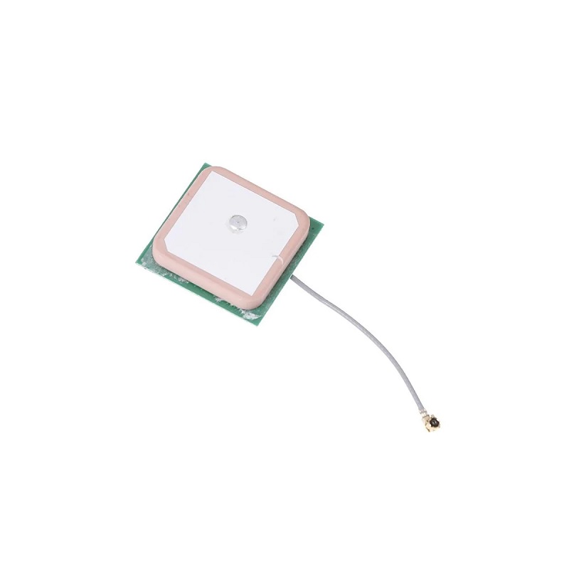
The Active Ceramic GPS Antenna with U.FL Interface Cable is designed for GPS signal reception in navigation, positioning and timing systems. It operates at 1575.42MHz ± 4MHz, corresponding to the GPS L1 frequency band, and uses right-hand circular polarization (RHCP) for receiving compatible GPS signals. Its ceramic antenna element and integrated active antenna design support installation in GPS receiver assemblies requiring an externally connected antenna.
The antenna features a 140mm cable terminated with a U.FL interface for connection to compatible GPS receiver boards and RF modules. Its listed RF characteristics include 28dB gain and a 1.5dB noise figure. The specified operating temperature range is -45°C to +85°C, while the storage temperature range is -50°C to +85°C.
The compact RF connection and active antenna configuration make this assembly suitable for GPS-enabled equipment, including marine navigation, positioning and timing applications. Compatibility depends on the receiver’s RF connector, frequency support, polarization and active antenna power requirements.
Ceramic Antenna Design & Active Signal Reception
The antenna uses a ceramic radiating element configured for GPS L1 signal reception. Its right-hand circular polarization is intended for use with GPS receiver systems designed for RHCP antennas. The active antenna arrangement incorporates signal amplification to support the receiver’s antenna input requirements.
- Ceramic Antenna Element: Antenna construction designed for GPS L1 signal reception.
- Active Antenna Configuration: Integrated active circuitry for RF signal amplification.
- GPS L1 Reception: Tuned for the 1575.42MHz GPS frequency region.
- RHCP Polarization: Right-hand circular polarization for compatible GPS receiving systems.
- Listed Gain: 28dB gain as provided in the product specifications.
- Noise Figure: Listed at 1.5dB.
RF Frequency & Interface Configuration
The antenna operates around the GPS L1 frequency of 1575.42MHz, with a specified frequency tolerance of ±4MHz. Its cable terminates in a U.FL RF interface, a compact connector commonly used on GPS receiver boards and embedded wireless modules. The receiver must have a matching U.FL mating connector and support the antenna’s active configuration.
- Operating Frequency: 1575.42MHz ± 4MHz.
- Frequency Band: GPS L1.
- Polarization: Right-hand circular polarization (RHCP).
- RF Connector Interface: U.FL.
- Cable Length: 140mm.
- Antenna Type: Active ceramic GPS antenna.
- Receiver Integration: Compatible GPS receiver with matching RF interface and active antenna support required.
Environmental & Operating Characteristics
The antenna is specified for operation across a temperature range of -45°C to +85°C and storage between -50°C and +85°C. The source also lists an optimum relative humidity range of 95%–100%. This humidity figure does not establish a waterproof or immersion-protection rating; the complete antenna assembly and its installation must be evaluated separately for environmental exposure.
- Operating Temperature: -45°C to +85°C.
- Storage Temperature: -50°C to +85°C.
- Listed Relative Humidity: 95%–100%.
- Environmental Integration: Suitable for equipment designed to operate within the specified temperature range.
Applications
This active ceramic GPS antenna is intended for electronic systems that require compatible GPS L1 signal reception. Its U.FL cable interface supports integration with appropriately equipped receiver boards and embedded navigation electronics.
- Marine Navigation Equipment: GPS signal reception for compatible marine navigation systems.
- GPS Receiver Modules: External antenna integration with receiver modules featuring a matching U.FL interface.
- Embedded GPS Systems: Antenna integration in compact electronic products with GPS functionality.
- Positioning Equipment: GPS signal reception for compatible location-determination systems.
- Timing Systems: Antenna input for GPS-based timing and synchronization equipment.
- Navigation Electronics: Integration into GPS-enabled navigation devices.
- Marine Tracking Systems: GPS antenna integration in compatible vessel tracking equipment.
- Vehicle Tracking Equipment: GPS reception for compatible tracking units.
- Portable GPS Devices: External antenna connection for receiver designs with matching RF interfaces.
- Industrial GPS Receivers: Integration into compatible industrial positioning and monitoring equipment.
- Surveying Electronics: GPS signal input for receiver equipment designed around the specified L1 frequency and antenna characteristics.
- Remote Monitoring Systems: GPS reception for compatible equipment requiring location or timing data.
- Navigation System Prototyping: Antenna integration and evaluation in GPS receiver development setups.
- GPS Hardware Testing: Evaluation of receiver and antenna performance in compatible RF test arrangements.
Package Includes
- 1 × Active Ceramic GPS Antenna with U.FL Interface Cable
Product Specifications
| Parameter | Specification |
|---|---|
| Product Type | Active GPS Antenna |
| Antenna Construction | Ceramic antenna element |
| Navigation System | GPS |
| Frequency Band | GPS L1 |
| Centre Frequency | 1575.42MHz |
| Frequency Tolerance | ±4MHz |
| Polarization | Right-Hand Circular Polarization (RHCP) |
| Listed Antenna Gain | 28dB |
| Noise Figure | 1.5dB |
| Antenna Interface | U.FL RF connector |
| Cable Length | 140mm |
| Antenna Operation | Active |
| Operating Temperature | -45°C to +85°C |
| Storage Temperature | -50°C to +85°C |
| Listed Relative Humidity | 95%–100% |
| Primary Application | GPS navigation, positioning and timing |
| Marine Application | Marine GPS navigation systems |
| Package Quantity | 1 antenna assembly |
Connection & Operating Recommendations
- Verify U.FL Compatibility: Confirm that the receiver board has a matching U.FL mating connector before installation. U.FL is a small RF connector family; do not force an incompatible connector into place.
- Check Active Antenna Power: Confirm the receiver provides the required antenna-bias supply and that its voltage and current are compatible with the antenna. The supply requirements are not specified here.
- Match Polarization: Use with a receiver antenna arrangement designed for RHCP GPS reception.
- Confirm Frequency Support: Ensure the GPS receiver supports the 1575.42MHz L1 frequency.
- Handle the Cable Carefully: Avoid sharp bends, excessive pulling and repeated stress on the U.FL connector.
- Position for Satellite Reception: Install the antenna with an appropriate view of the sky and minimize obstruction by metal structures or other shielding materials.
- Protect the RF Connection: Secure the connector and cable to prevent mechanical strain during equipment operation.
- Evaluate Environmental Protection: For marine or outdoor installations, provide suitable enclosure and sealing protection. No IP or waterproof rating is specified.
- Check Receiver Performance: Verify satellite acquisition and signal quality after installation in the final equipment configuration.