
SPIDER Automation | MB102 830-Point Transparent Solderless Breadboard | Electronic Circuit Prototyping Platform
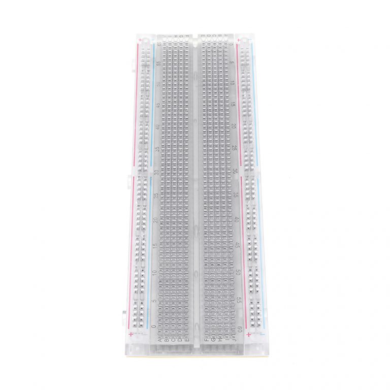
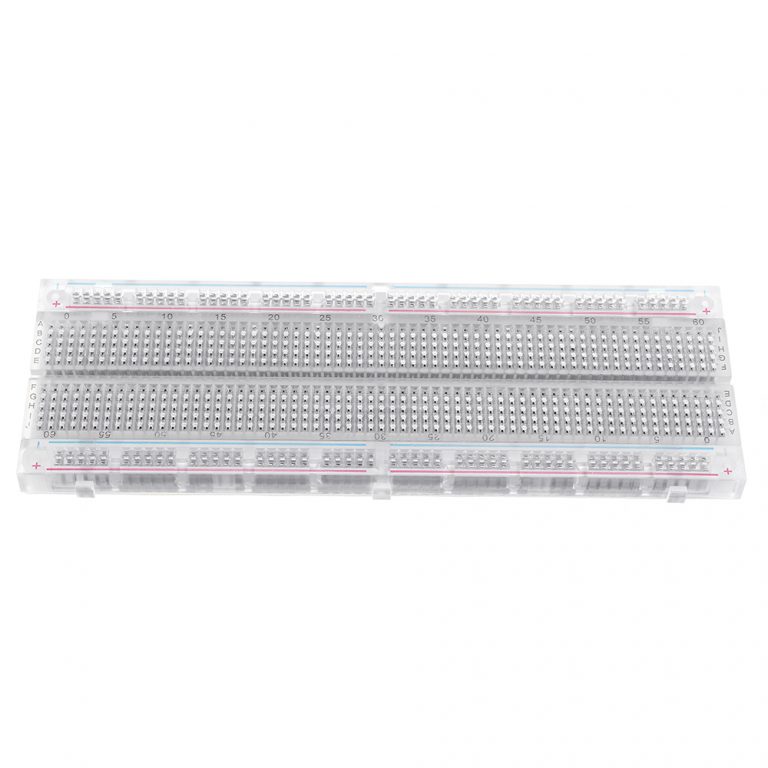
The SPIDER Automation MB102 830-Point Transparent Solderless Breadboard is a reusable prototyping platform for assembling, testing and modifying electronic circuits without permanent soldered connections. Its 830-point configuration combines a 630-point central terminal section with 200 power distribution points, providing dedicated areas for component placement and supply wiring. The MB102 format is widely used in electronics development, engineering laboratories, university projects and circuit experimentation where connections need to be changed frequently.
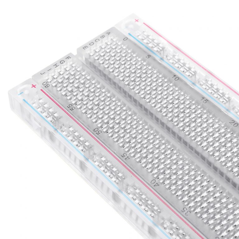
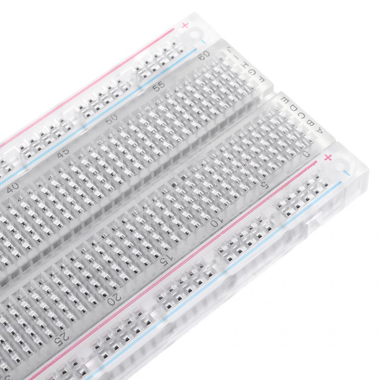
The breadboard features an ABS plastic housing with nickel-plated phosphor bronze spring contacts designed for reusable plug-in connections. Its transparent construction provides visibility of the internal contact arrangement, while coloured coordinate markings help organise component placement and wiring. Measuring 165 × 55 × 10mm, the board accommodates compatible through-hole components and jumper wires within a stated 20–29 AWG range, supporting practical circuit assembly and repeated prototype revisions.
Product Overview & Functional Design
The MB102 solderless breadboard provides a temporary electrical connection platform for developing electronic circuits without soldering components directly onto a PCB. Component leads and compatible jumper wires are inserted into the contact openings, allowing circuit arrangements to be assembled, tested and modified as required.
Its 830-point layout is divided into two main functional areas:
- Central Terminal Area – 630 Points: Provides the main component placement and connection region for assembling electronic circuits.
- Power Distribution Area – 200 Points: Provides dedicated distribution points for organising supply and return wiring.
The standard MB102 arrangement is designed around the commonly used 2.54mm (0.1-inch) component spacing, supporting many through-hole electronic components and prototyping accessories.
Technical Features & Contact Construction
- 830-Point Connection Capacity: Combines 630 terminal points and 200 power distribution points in one prototyping board.
- Nickel-Plated Phosphor Bronze Contacts: Spring contacts provide the internal plug-in connection interface for compatible component leads and jumper wires.
- Reusable Contact Arrangement: Supports repeated component insertion, removal and circuit modification without soldering.
- ABS Housing: Provides the plastic structure that holds and supports the breadboard contact arrangement.
- Transparent Body: Allows the internal contact construction to be viewed through the housing.
- Coloured Coordinate Markings: Help users identify positions and organise component placement during circuit assembly.
- MB102 Breadboard Format: Provides a familiar prototyping layout for compatible electronics development accessories.
- 20–29 AWG Wire Range: Supports a variety of compatible jumper wire sizes for circuit connections.
Component & Jumper Wire Compatibility
The MB102 breadboard is intended for temporary assembly of circuits using compatible through-hole components and jumper wires. Its standard component spacing supports commonly used electronic parts, while the central terminal area and power distribution sections help organise circuit connections.
- Resistors: Compatible through-hole resistor leads for circuit assembly and testing.
- Capacitors: Suitable through-hole capacitor leads within the contact and spacing limits.
- Diodes: Supports compatible diode packages for circuit development.
- LEDs: Accommodates compatible through-hole LED leads for indicator and lighting circuits.
- Transistors: Supports compatible through-hole transistor packages, subject to lead spacing and physical dimensions.
- Jumper Wires: Designed for compatible wire sizes within the stated 20–29 AWG range.
Component compatibility depends on lead thickness, spacing and package dimensions. Components with unusually thick leads or incompatible pin arrangements should not be forced into the contact openings.
Mechanical Construction & Layout Identification
The board uses a transparent ABS housing and an internal contact system made from nickel-plated phosphor bronze spring clips. This contact construction is designed to hold compatible inserted leads and jumper wires while allowing connections to be changed during circuit development.
Coloured coordinate markings on the top surface assist with component positioning and circuit documentation. The 165 × 55mm footprint provides a relatively extended prototyping area for arranging multiple components and wiring connections in an organised layout.
Applications
The MB102 830-point solderless breadboard is suitable for electronics prototyping, laboratory experiments and preliminary circuit development where temporary connections and repeated modifications are required.
- Microcontroller Prototyping: Assemble temporary circuits around compatible microcontroller boards and supporting components.
- Arduino Circuit Development: Build and test compatible Arduino-based interface, indicator and control circuits.
- Digital Logic Experiments: Develop and evaluate digital logic arrangements using compatible through-hole components.
- Analogue Circuit Prototyping: Assemble basic analogue circuits, signal-conditioning stages and component networks.
- Sensor Interface Testing: Connect compatible sensors and supporting circuitry for preliminary functional evaluation.
- Power Distribution Experiments: Use the dedicated power sections to organise supply wiring for suitable low-voltage prototype circuits.
- LED and Indicator Circuits: Assemble LED arrangements, indicator circuits and associated resistor networks.
- Component Evaluation: Test compatible resistors, capacitors, diodes and transistors in temporary circuit configurations.
- University and Engineering Laboratories: Support practical electronics experiments, circuit demonstrations and laboratory development work.
- R&D Circuit Development: Evaluate circuit concepts and revise component arrangements before producing a permanent PCB.
- Preliminary Hardware Validation: Check basic circuit functionality and wiring arrangements during early-stage engineering development.
Package Includes
- 1 × MB102 830-Point Transparent Solderless Breadboard
The package contains one transparent breadboard only. Jumper wires, electronic components, development boards, power supplies and other prototyping accessories are not included.
Product Specifications
| Parameter | Specification |
|---|---|
| Product Type | Solderless electronic prototyping breadboard |
| Model | MB102 |
| Total Tie Points | 830 |
| Terminal Points | 630 |
| Power Distribution Points | 200 |
| Component / Hole Pitch | 2.54mm (0.1 inch), standard MB102 format |
| Housing Material | ABS plastic |
| Contact Material | Phosphor bronze |
| Contact Surface Plating | Nickel-plated |
| Contact Type | Spring clips |
| Connection Method | Solderless plug-in connections |
| Body Transparency | Transparent |
| Top Surface Markings | Coloured coordinate markings |
| Allowed Wire Size | 20–29 AWG |
| Board Length | 165mm |
| Board Width | 55mm |
| Board Height | 10mm |
| Product Weight | 95g |
| Package Quantity | 1 breadboard |
Connection & Operating Recommendations
- Check Lead and Wire Dimensions: Use compatible component leads and jumper wires within the stated 20–29 AWG range. Avoid forcing oversized leads into the contact openings.
- Verify the Contact Layout: Check the breadboard’s internal connection arrangement before wiring power, ground and component connections.
- Disconnect Power Before Modifications: Switch off the circuit supply before inserting, removing or rearranging components and jumper wires.
- Check Polarity and Wiring: Verify component orientation, supply polarity and circuit connections before energising the prototype.
- Use Suitable Low-Voltage Supplies: Select supply voltage and current appropriate to the components and circuit being tested. Do not use the breadboard for mains-voltage wiring.
- Distribute Power Carefully: Check supply and return connections along the power distribution sections before connecting the complete circuit.
- Avoid Excessive Insertion Force: Insert and remove components carefully to minimise stress on the leads and internal spring contacts.
- Inspect Contact Condition: Check for loose connections or damaged contacts if a circuit behaves intermittently during testing.