
SPIDER Automation | 7-Pin JST-VH Male-Female Connector Set | 3.96mm Pitch Electrical Wiring Interface
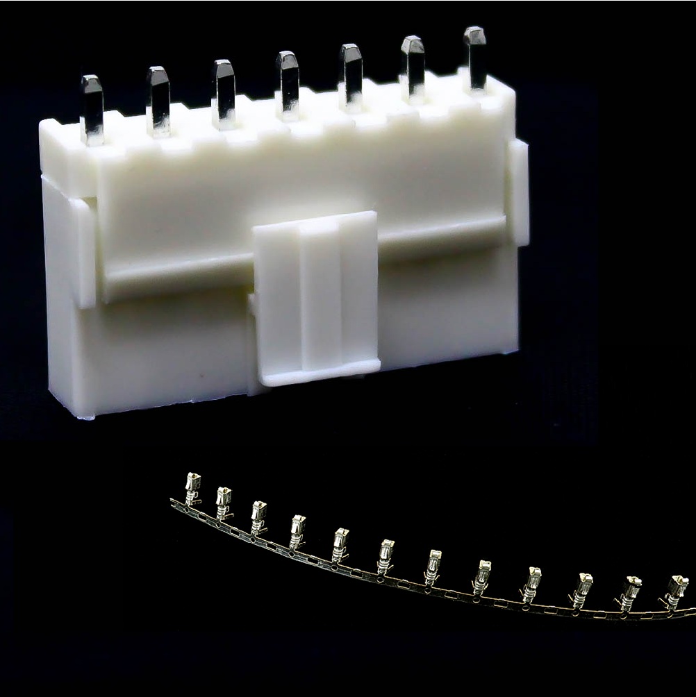
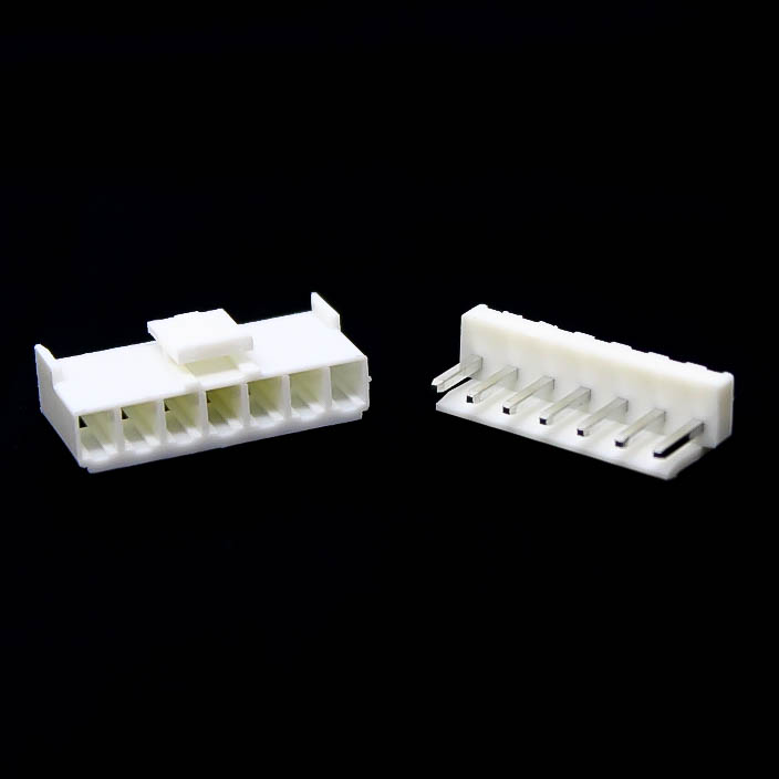
The SPIDER Automation 7-Pin JST-VH Connector Set is designed for multi-conductor electrical connections in compatible battery assemblies, electronic equipment and control-system wiring. Its seven-position contact arrangement groups multiple electrical paths into one mating interface, simplifying connections between wiring harnesses, circuit boards and equipment modules. The 3.96mm contact pitch defines the spacing between adjacent positions and is an important mechanical parameter when selecting the matching connector.
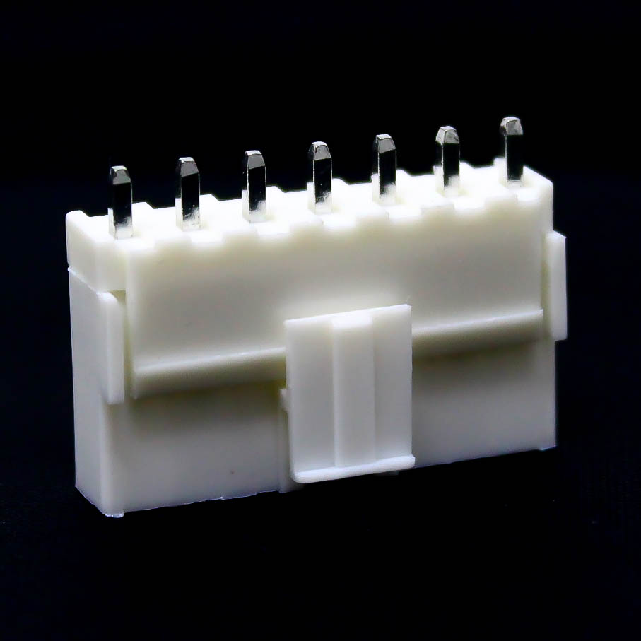
The connector assembly uses phosphor bronze contacts with nickel plating and a white plastic housing carrying a stated UL94V-0 flammability classification. Its specified electrical characteristics include 250V DC operating voltage and 3A current handling capacity, with an operating temperature range of −25°C to +85°C. The male-female arrangement supports detachable connections, while the approximate housing dimensions of 28 × 8 × 19mm and individual weight of 3g make it suitable for compact equipment wiring arrangements.
Product Overview & Seven-Contact Configuration
The seven-position connector provides a grouped connection interface for applications requiring seven separate electrical paths through one connector assembly. This arrangement allows multiple conductors to be connected or disconnected together, which can simplify harness assembly and servicing compared with handling individual wire connections.
The 3.96mm pitch is a key fitment dimension for the mating interface. Correct compatibility also depends on the connector-family profile, contact geometry, housing dimensions and terminal arrangement. A connector with the same number of positions but a different series or pitch may not mate correctly.
Contact Construction & Electrical Characteristics
The contact system uses phosphor bronze as its conductive material, with a specified nickel-plated finish. These contacts form the electrical connection between corresponding male and female components when the connector is correctly mated. Suitable terminal selection, conductor preparation and secure termination are important for maintaining dependable electrical continuity.
The specified operating voltage is 250V DC, and the stated current handling capacity is 3A. These ratings must be considered alongside conductor size, ambient temperature, contact loading and the electrical requirements of the connected equipment. The 3A rating should not be interpreted as confirmation that all seven contacts can simultaneously carry 3A under every operating condition.
Housing Construction & Operating Temperature
The connector uses a white plastic housing with a stated UL94V-0 flammability classification. This classification relates to material performance under the UL94 vertical-burning test and should not be confused with an ingress-protection rating or environmental sealing specification.
The specified operating temperature range is −25°C to +85°C. This range provides a reference for selecting the connector in compatible electronic assemblies and equipment wiring systems.
Applications
The seven-position connector format is useful in equipment designed around a matching 3.96mm male-female connection interface. Typical applications include:
- Rechargeable Battery Assemblies: Multi-conductor connections in compatible battery-pack wiring arrangements.
- Battery Balancer Equipment: Grouped connections for battery monitoring and balancing systems with matching connector pinouts.
- Electronic Control Boards: Board-to-wire connections between compatible control circuits and external wiring harnesses.
- Industrial Equipment Harnesses: Multi-position wiring interfaces in compatible machine and equipment assemblies.
- Power-System Wiring: Grouped conductor connections in equipment designed within the connector’s applicable electrical limits.
- Embedded Electronics: Connections between controller boards, electronic modules and external wiring assemblies.
- RC Equipment: Multi-wire connections in compatible radio-controlled equipment using the matching connector interface.
- Equipment Maintenance: Replacement of damaged connector assemblies in compatible electronic and electrical systems.
- Custom Wiring Harnesses: Seven-conductor connection points for equipment-specific harness fabrication.
Package Includes
- 7-Pin JST-VH Male-Female Connector: Pack of 5 connector units.
Product Specifications
| Parameter | Specification |
|---|---|
| Product Type | Male-female electrical connector with housing |
| Connector Family | JST-VH designation (verify family before mating) |
| Contact Configuration | 7-pin |
| Contact Pitch | 3.96mm |
| Connector Gender | Male-female configuration |
| Operating Voltage | 250V DC (stated rating) |
| Current Handling Capacity | 3A (stated rating) |
| Contact Material | Phosphor bronze |
| Contact Plating | Nickel |
| Housing Material | Plastic |
| Housing Colour | White |
| Flammability Classification | UL94V-0 |
| Operating Temperature | −25°C to +85°C |
| Metal Connector Size | 7.5mm (stated dimension) |
| Length | 28mm |
| Width | 8mm |
| Height | 19mm |
| Individual Weight | Approximately 3g each |
| Package Quantity | 5 connector units |
Connection & Operating Recommendations
- Verify Connector Series: Confirm that the mating component is the correct 3.96mm JST-VH-compatible interface. Do not rely on contact pitch alone when selecting the connector.
- Check Contact Count: Ensure that both connector halves have the required seven-position arrangement and matching contact geometry.
- Confirm Pin Assignment: Check the equipment wiring diagram before connecting, particularly in battery and power circuits where incorrect polarity or pin mapping can damage connected components.
- Select Suitable Wire: Use conductors and compatible crimp terminals appropriate for the intended electrical load and operating environment.
- Inspect Terminations: Check terminal retention and conductor termination quality to ensure secure electrical connections.
- Align Before Mating: Match the connector orientation and housing profile before insertion. Avoid forcing mismatched connector halves together.
- Observe Electrical Limits: Keep the circuit within applicable voltage and current limits, accounting for contact loading and thermal conditions.
- Disconnect Power Before Servicing: Isolate the equipment supply before connecting, disconnecting or replacing the connector assembly.
- Inspect During Maintenance: Check for bent contacts, damaged housings, loose terminals and contamination before reconnecting.
- Support the Wiring Harness: Provide suitable cable support to reduce pulling and bending forces at the connector interface.