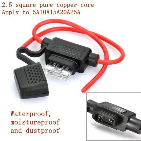

SPIDER Automation | In-Line Automotive Blade Fuse Holder Set | Mini, Standard & Maxi Fuse Formats
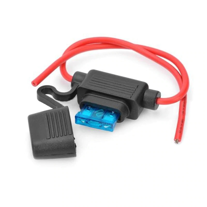
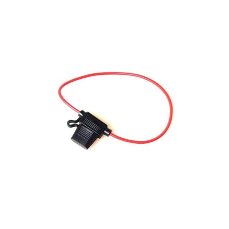
The SPIDER Automation In-Line Automotive Blade Fuse Holder Set provides pre-assembled receptacle holders for integrating replaceable blade fuses into automotive and other suitable low-voltage electrical wiring systems. The holder range is described for Mini, Standard and Maxi blade fuse formats, with the corresponding holder configuration selected according to the physical fuse size and required electrical rating. The receptacle contacts are manufactured from brass with a tin-plated finish and assembled to an insulating base made from UL 94V-0-rated glass-filled nylon.
The contact arrangement is designed to retain the inserted blade fuse and provide electrical connection through its terminals. The specified cable size is 16 AWG, with a maximum voltage drop of 20mV, minimum insulation resistance of 100MΩ at 500V DC and minimum dielectric strength of 1500V AC for 60 seconds. These characteristics support selection and integration into compatible fuse-protected wiring assemblies. The supplied package contains five holders; the correct fuse format, current rating and voltage suitability must be verified for each installation.
Product Overview & Fuse Holder Design
An in-line blade fuse holder provides a removable connection point for a compatible automotive blade fuse within an electrical circuit. When the correct fuse is installed, it provides an accessible, replaceable overcurrent protection element without requiring the fuse to be soldered directly into the wiring assembly.
This holder range uses two receptacle terminals assembled to an insulating base. The receptacle contacts receive the blade-fuse terminals and are designed to maintain secure engagement. Separate pre-assembled configurations are described for Mini, Standard and Maxi blade fuse formats, so the holder must be matched to the physical fuse type rather than treated as a universal socket.
Terminal Construction & Insulation
- Brass Receptacle Terminals: Conductive brass contacts provide the electrical interface with the inserted blade fuse.
- Tin-Plated Contact Finish: The terminal finish is specified as tin-plated for the fuse contact interface.
- Glass-Filled Nylon Base: The insulating base uses nylon reinforced with glass fibre for the holder structure.
- UL 94V-0 Material Classification: The base material is identified with a UL 94V-0 flammability classification.
- Secure Fuse Engagement: Receptacle contacts are designed to hold the compatible fuse terminals in position.
- Pre-Assembled Construction: The receptacle terminals and insulating base are supplied as an assembled holder unit.
- 16 AWG Wiring: The specified cable size supports integration into compatible wiring assemblies.
Electrical Performance Characteristics
The specified electrical performance values provide reference points for evaluating the holder in a compatible circuit. The maximum voltage drop and minimum insulation resistance describe different aspects of electrical performance: voltage drop relates to the conductive path, while insulation resistance relates to isolation between conductive and non-conductive portions under the stated test conditions.
- Maximum Voltage Drop – 20mV: Specifies the stated maximum voltage drop across the applicable holder contact path under its test conditions.
- Minimum Insulation Resistance – 100MΩ: Specified at a test voltage of 500V DC.
- Dielectric Strength – 1500V AC: Specified minimum withstand test for a duration of 60 seconds.
- Temperature Rise – 50 Maximum: The source specifies a maximum temperature-rise value of 50; the unit and test conditions are not provided.
- Insertion and Extraction Force – 1kg Minimum: The stated minimum force requirement for fuse insertion and removal is 1kg.
Fuse Format & Application Configurations
The holder range is described for multiple automotive blade-fuse formats. Physical compatibility and electrical ratings must be checked independently before installation.
- Mini Blade Fuse Holder: The source describes a Mini-format holder for applications up to 30A.
- Standard Blade Fuse Holder: The source describes a Standard-format holder for applications up to 40A.
- Maxi Blade Fuse Holder: The source describes a Maxi-format holder for applications up to 60A.
- ATO / FKS Fuse-Link Applications: The described application configurations include holders for ATO / FKS-size fuse-links, including crimp-terminal and solderable-contact arrangements.
- TAC Fuse-Link Applications: A separate application description identifies a holder configuration for TAC fuse-links in a 42V PowerNet context.
These application descriptions refer to different holder configurations and terminal arrangements. They should not be interpreted as confirmation that every holder in the package supports every listed fuse format, terminal style or current rating. Verify the actual supplied holder configuration before selecting a fuse or preparing the wiring.
Applications
These in-line blade fuse holders are intended for electrical assemblies that require a replaceable fuse connection and a compatible insulated receptacle arrangement.
- Automotive Wiring Protection: Integrate compatible blade fuses into vehicle electrical wiring circuits.
- Automotive Accessory Circuits: Provide a replaceable fuse connection for appropriately rated accessory wiring.
- Vehicle Electrical Maintenance: Replace damaged or worn holders where the fuse format and electrical specifications match the original installation.
- Low-Voltage Power Wiring: Incorporate a compatible fuse holder into suitable low-voltage DC distribution circuits.
- Automotive Control Assemblies: Add a replaceable fuse interface to compatible control and electrical subassemblies.
- Auxiliary Electrical Systems: Provide fuse mounting for suitable auxiliary vehicle electrical equipment.
- ATO / FKS Fuse-Link Assemblies: Use the corresponding holder configuration in compatible fuse-link installations.
- Mini Blade Fuse Installations: Use the Mini-format holder where the fuse dimensions and electrical ratings match.
- Standard Blade Fuse Installations: Use the Standard-format holder in compatible automotive fuse circuits.
- Maxi Blade Fuse Installations: Use the Maxi-format holder for compatible higher-current automotive fuse arrangements.
Package Includes
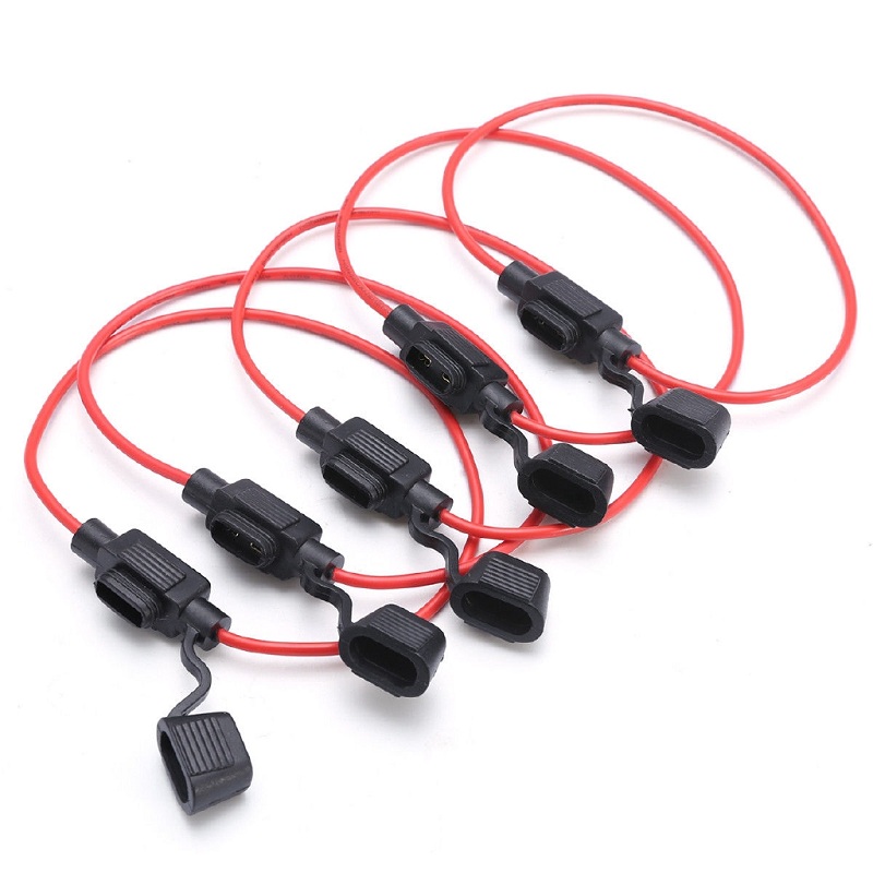
- 5 × In-Line Automotive Blade Fuse Holders
The package includes five fuse holders. Blade fuses and additional wiring accessories are not identified as included.
Product Specifications
| Parameter | Specification |
|---|---|
| Product Type | In-line automotive blade fuse holder |
| Holder Configurations | Mini, Standard and Maxi blade fuse formats |
| Contact Arrangement | Two receptacle terminals per holder |
| Terminal Material | Brass |
| Terminal Finish | Tin-plated |
| Base Material | Glass-fibre-reinforced nylon |
| Base Material Classification | UL 94V-0 |
| Cable Size | 16 AWG |
| Rated Current Range | 5–25A |
| Suitable Rated Current | 30A maximum |
| Mini Holder Current Description | 30A application rating |
| Standard Holder Current Description | 40A application rating |
| Maxi Holder Current Description | 60A application rating |
| Insertion / Extraction Force | 1kg minimum |
| Dielectric Strength | 1500V AC minimum for 60 seconds |
| Insulation Resistance | 100MΩ minimum at 500V DC |
| Temperature Rise | 50 maximum |
| Voltage Drop | 20mV maximum |
| PCB Snap-In Type References | WGP20, WGP29 |
| PCB Quick-Insert Terminal References | WGP21, WGP22, WGP23, WGP24, WGP25, WGP26, WGP27, WGP28, WGS01, WGS02 |
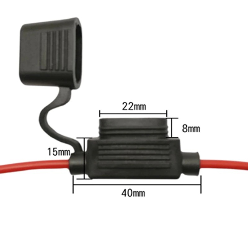
| Overall Length | 300mm |
| Overall Width | 35mm |
| Height | 2.6mm |
| Specified Weight | 110g |
| Package Quantity | 5 holders |
Installation & Operating Recommendations
- Confirm the Fuse Format: Match the holder to the exact Mini, Standard or Maxi blade fuse dimensions. Do not force a different fuse format into the receptacle.
- Verify the Current Rating: Confirm the actual holder variant’s current rating before installation. The supplied general specification and the separate Mini, Standard and Maxi ratings are inconsistent and should not be treated as interchangeable.
- Check Circuit Voltage: Verify the holder’s applicable voltage rating for the intended AC or DC circuit before use. Do not infer a voltage rating from the insulation test voltage.
- Use the Specified Cable Size: Select compatible 16 AWG wiring and use an appropriate termination method for the actual holder configuration.
- Confirm Terminal Configuration: The application descriptions include different crimp and solderable terminal arrangements. Check the supplied holder type before preparing wire connections.
- Use a Correctly Rated Fuse: Select a fuse with an appropriate current rating and breaking capacity for the protected circuit. The holder’s maximum current description does not determine the correct fuse rating by itself.
- Inspect Fuse Engagement: Ensure that the fuse terminals are fully seated and held securely by the receptacle contacts.
- Protect Against Environmental Exposure: Although the product is described as waterproof, no sealing construction, IP rating or water-ingress test specification is provided. Do not rely on it for exposed wet-environment installations without independent verification.
- Disconnect Power Before Servicing: Isolate the circuit before inserting, removing or replacing a fuse or modifying wiring.
- Check for Overheating: Inspect terminals and wiring for looseness, discolouration or abnormal heating during maintenance.