
SPIDER Automation | PCT-SPL-62 6-to-2 Pole Spring Lever Wire Connector | Multi-Conductor Electrical Splicing Terminal
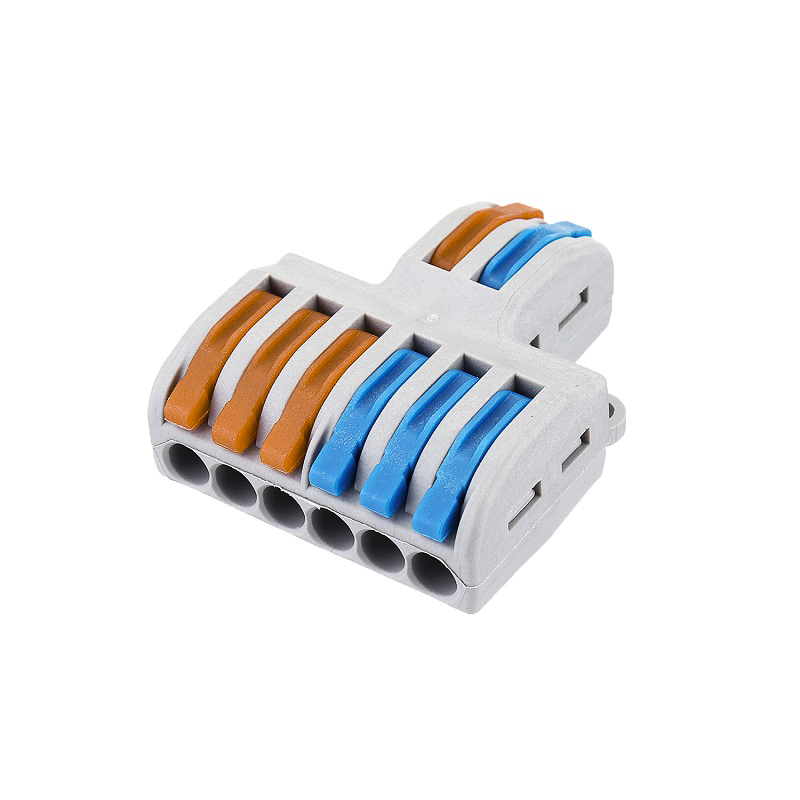
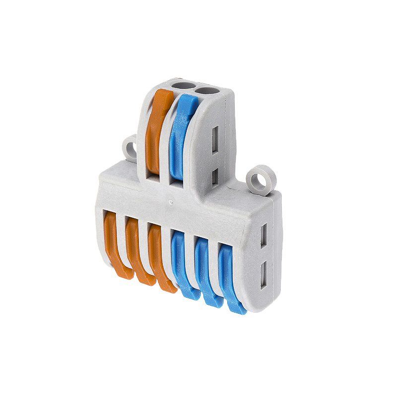
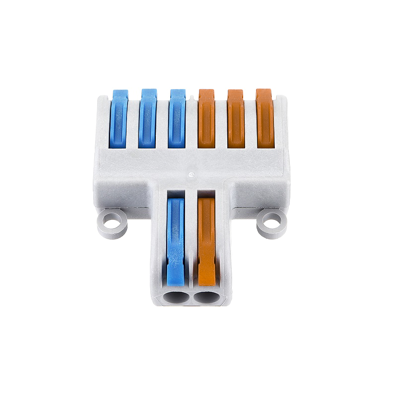
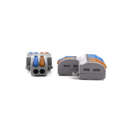
The SPIDER Automation PCT-SPL-62 Spring Lever Wire Connector is a multi-conductor electrical terminal designed for organised wire joining and distribution in electrical wiring assemblies. Its distinctive 6-to-2 pole configuration provides six conductor positions on one side and two on the other, allowing compatible wiring arrangements to be consolidated within a single connector body. The spring-operated lever mechanism controls conductor retention, simplifying wire insertion and release compared with conventional screw-clamping terminal arrangements.
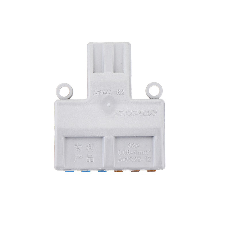
Constructed with a modified PA66 nylon insulating housing and internal stainless-steel contacts, the connector supports solid conductors from 0.08–2.5mm² and flexible conductors from 0.08–4mm². It has a stated current rating of 32A, a specified operating temperature range of −20°C to +80°C and an overall length of 40mm. Its multi-position connection layout is useful for compact electrical distribution arrangements where conductor organisation and convenient access to individual connection levers are important.
Product Overview & 6-to-2 Connection Architecture
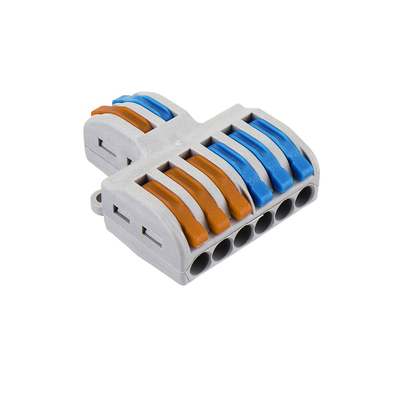
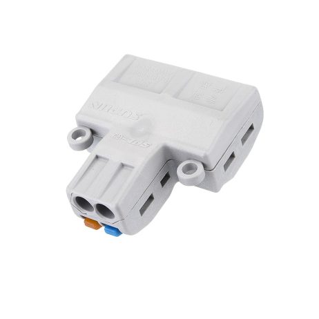
The PCT-SPL-62 is designed around a six-to-two conductor connection arrangement. This configuration provides six connection positions on one side and two on the opposite side, supporting wiring layouts that require multiple conductors to be joined or distributed through a common terminal assembly.
Unlike a simple single-input, single-output connector, the 6:2 arrangement provides multiple conductor entry positions for more complex splicing layouts. The exact circuit assignment must be established from the connector’s physical terminal arrangement and wiring diagram before installation. The number of conductor positions should not be interpreted as an indication of independent electrical circuits or a specific internal circuit topology without confirmation.
Spring Lever Contact Mechanism
The connector uses a lever-operated spring contact mechanism to retain inserted conductors. Operating a lever releases the corresponding spring contact, allowing a prepared conductor to be inserted or removed. Returning the lever to its closed position engages the spring mechanism and retains the conductor at the contact interface.
This arrangement reduces dependence on screw tightening and makes individual conductor handling more convenient during wiring assembly and maintenance. It is particularly useful where multiple connections must be made within a limited enclosure space. Correct conductor preparation, full insertion and proper lever engagement remain essential for reliable electrical contact.
Insulating Housing & Contact Construction
The external housing is manufactured from modified Nylon (PA66), an engineering polymer used for electrical connector insulation and structural enclosure applications. It surrounds the internal conductive components and provides an insulating body for organising the conductor connection points.
The internal contacts are specified as stainless steel. These metal contact elements form the electrical interface with the inserted conductors and operate in conjunction with the spring mechanism. The combination of an insulating polymer housing and lever-controlled contacts creates a compact terminal assembly for compatible electrical distribution and equipment wiring.
Conductor Compatibility & Wiring Requirements
The connector supports the following conductor cross-section ranges:
- Solid conductors: 0.08–2.5mm².
- Flexible conductors: 0.08–4mm².
These limits are different for the two conductor categories and should be checked independently when selecting wiring. A conductor suitable for one connection type or cross-section must not automatically be assumed suitable for another. Prepare the wire ends carefully and ensure that the conductor is compatible with the terminal’s contact geometry.
Because the connector has a 6:2 arrangement, identify the correct side and connection position for every conductor before wiring. Confirm the required electrical distribution arrangement from the actual terminal layout rather than relying only on the number of connection openings.
Compact Mechanical Design & Installation Space
The connector has a stated 40mm overall length and a compact multi-position body. Its configuration is intended to consolidate several conductor connections within one assembly, helping organise wiring in suitable electrical boxes and equipment enclosures.
When planning an installation, allow adequate space for conductor routing and full movement of the operating levers. Avoid excessive bending or pulling forces on connected wires, as mechanical strain can affect conductor retention and the long-term stability of the connection.
Applications
The PCT-SPL-62 is suitable for compatible multi-conductor joining and distribution arrangements in electrical equipment and wiring assemblies.
- Multi-Conductor Junction Connections: Consolidates compatible conductor connections within a junction enclosure using its six-to-two terminal arrangement.
- Electrical Distribution Wiring: Supports organised conductor distribution where multiple wires must be connected through a common terminal assembly.
- Lighting Distribution Assemblies: Can be considered for compatible multi-wire lighting connections where the circuit layout matches the terminal configuration.
- Control Panel Wiring: Provides a compact spring-operated connection option for suitable multi-conductor control wiring arrangements.
- Electrical Enclosure Assemblies: Helps organise multiple conductor connections inside compatible electrical equipment enclosures.
- Equipment Power Wiring: Suitable for compatible conductor joining points in electrical equipment, subject to circuit and load requirements.
- Appliance Wiring Assemblies: Supports suitable multi-wire connection arrangements within compatible electrical appliances and equipment.
- Electrical Maintenance: Individual lever operation facilitates conductor release when authorised wiring modifications or replacements are required.
- Compact Wiring Systems: Useful where several conductor positions need to be accommodated within a limited installation area.
Package Includes
- PCT-SPL-62 6-to-2 Pole Spring Lever Wire Connector: 1 piece.
Product Specifications
| Parameter | Specification |
|---|---|
| Product Type | Spring lever wire connector terminal block |
| Series | PCT |
| Model | PCT-SPL-62 |
| Connection Configuration | 6-to-2 pole / conductor arrangement |
| Connection Mechanism | Spring-operated contact with levers |
| Rated Current | 32A |
| Rated Voltage | Conflicting values supplied: 400V in product description and 250V in specification table; verify before publication |
| Solid Conductor Cross-Section | 0.08–2.5mm² |
| Flexible Conductor Cross-Section | 0.08–4mm² |
| AWG Range | 28–12 AWG (overall stated range; confirm conductor-specific limits) |
| Housing Material | Modified Nylon (PA66) |
| Contact Material | Stainless steel |
| Available Colour Options | Blue, grey and orange; actual supplied colour may vary |
| Operating Temperature | −20°C to +80°C |
| Maximum Continuous Service Temperature | 85°C |
| Overall Length | 40mm |
| Rated Power Claim | 7kW stated; actual permissible load depends on verified voltage, current and installation conditions |
| Package Quantity | 1 piece |
Connection & Operating Recommendations
- Isolate the Power Supply: Disconnect the circuit and verify that it is de-energised before connecting, disconnecting or modifying any conductor.
- Confirm the 6:2 Layout: Identify the six-position and two-position sides and establish the intended circuit connections before inserting wires.
- Check Wire Compatibility: Use solid conductors within 0.08–2.5mm² or flexible conductors within 0.08–4mm², as applicable.
- Prepare Wire Ends: Strip insulation evenly to the required insertion depth without damaging conductor material or leaving loose strands.
- Operate the Correct Lever: Open the lever associated with the intended conductor position before inserting or removing a wire.
- Insert Conductors Fully: Position each conductor correctly in its designated opening and close the corresponding lever to engage the spring contact.
- Check Each Connection: Perform a gentle individual pull test and inspect the conductor entries to confirm secure retention and proper insertion.
- Verify Circuit Assignment: Confirm the electrical relationship between all connection positions using the actual wiring arrangement. Do not assume that the 6:2 configuration represents a particular internal circuit topology.
- Assess Electrical Loading: Consider the stated 32A current rating together with conductor cross-section, circuit protection, enclosure conditions and applicable wiring regulations.
- Maintain Temperature Limits: Keep the connector within its specified operating range of −20°C to +80°C and maximum continuous service temperature of 85°C.
- Allow Lever Clearance: Arrange the wiring so that each operating lever remains accessible and can move without obstruction.
- Inspect Before Energising: Check for exposed conductor strands, damaged insulation, incomplete insertion and unintended contact with adjacent conductive parts.