
SPIDER Automation u-blox NEO-7M GPS Module with HMC5883L Compass | GPS Navigation & Flight-Controller Positioning
Description
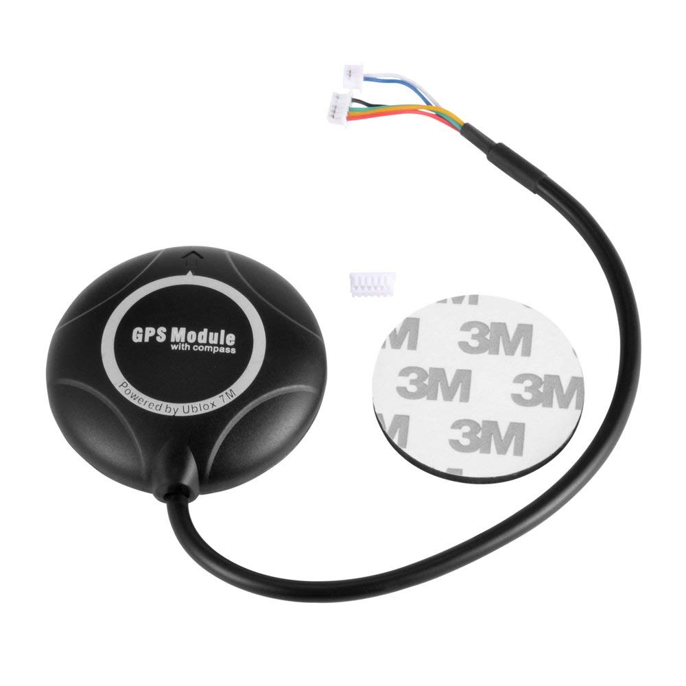
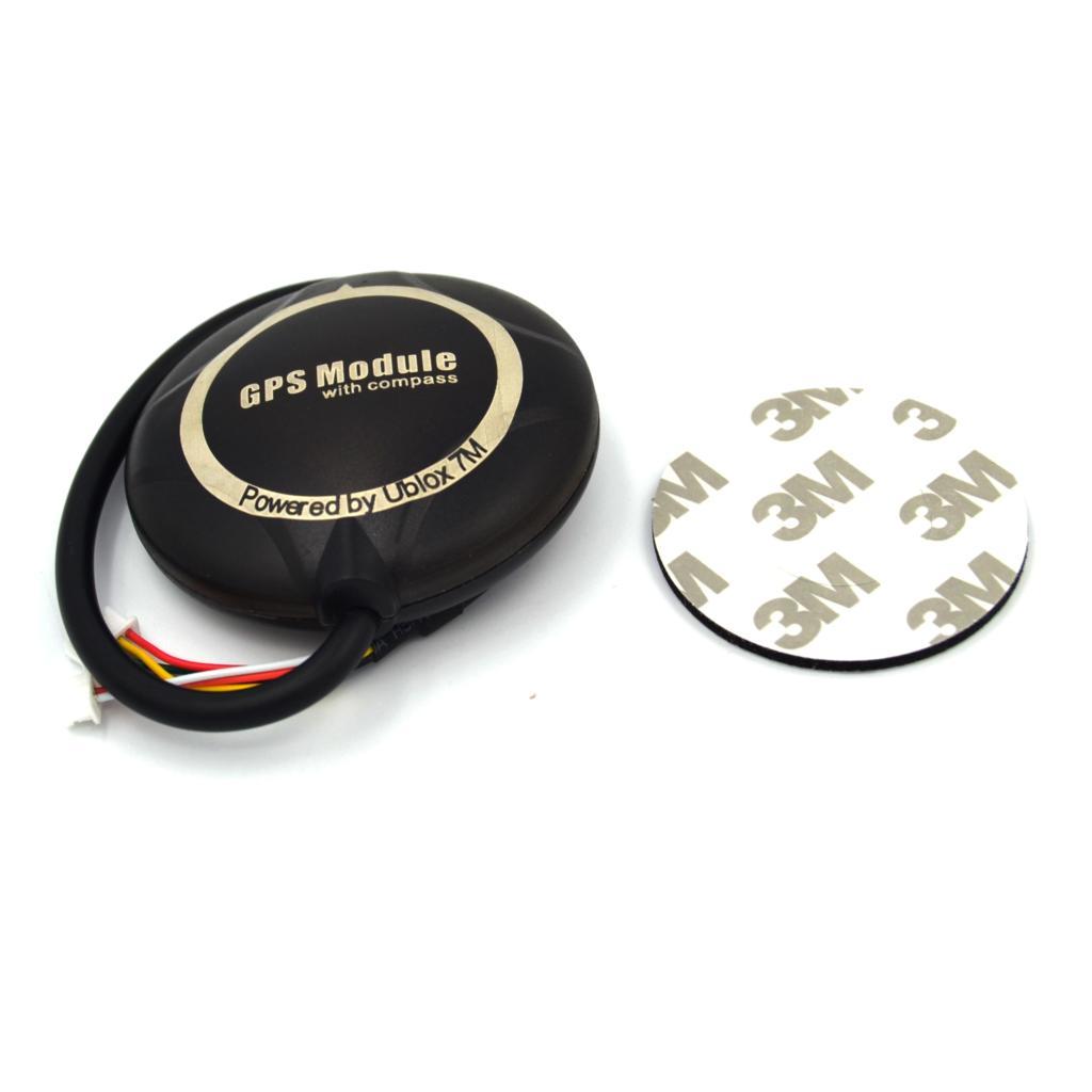
The SPIDER Automation u-blox NEO-7M GPS Module with HMC5883L Digital Compass combines satellite positioning and magnetic heading measurement in a compact navigation assembly for UAVs, multirotor aircraft and compatible flight-control platforms. It uses the u-blox NEO-7M GPS receiver to acquire positioning signals in the 1575.42MHz GPS L1 band and provides navigation data for flight-controller functions such as position hold, return-to-home, waypoint navigation and autonomous flight.
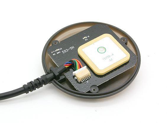
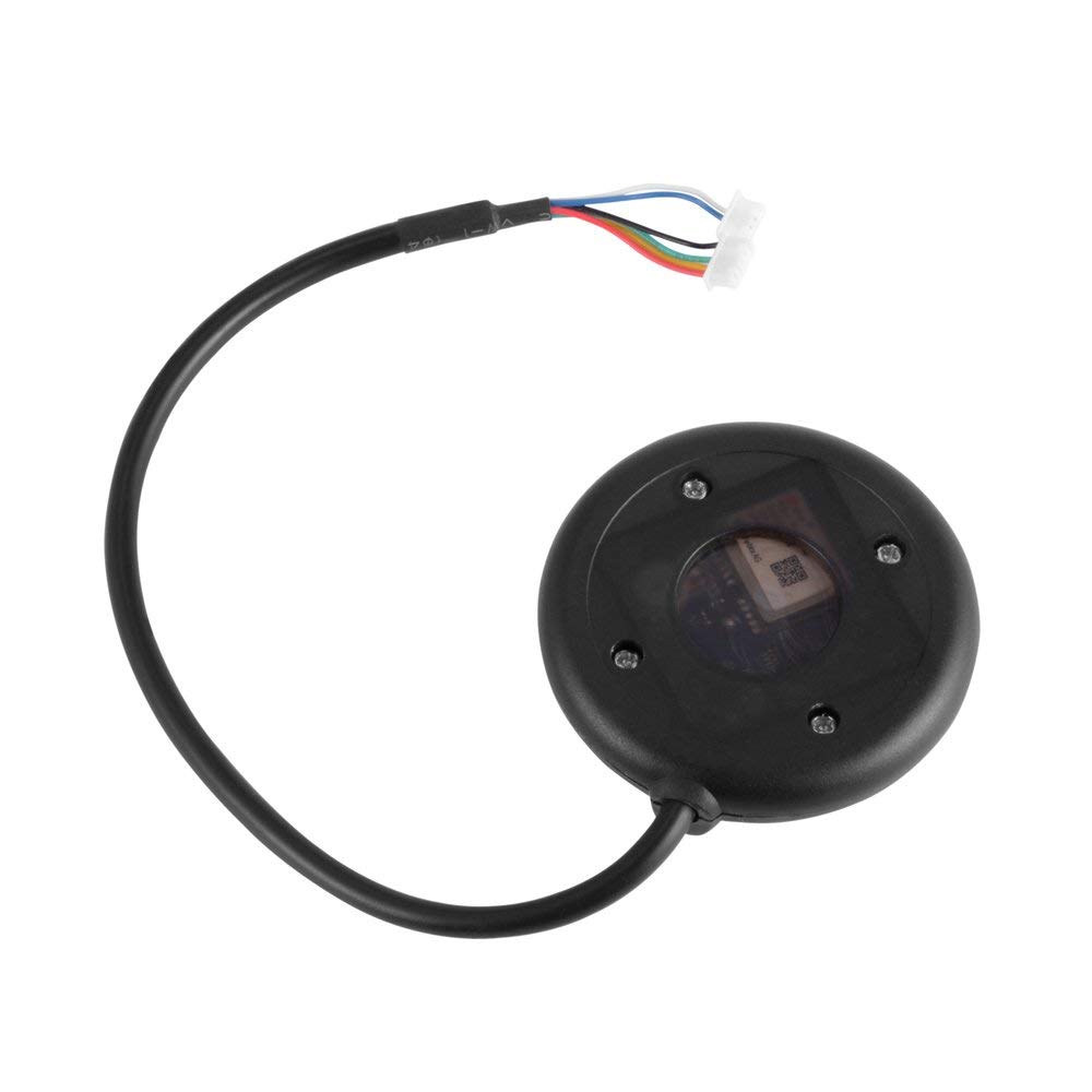
The integrated HMC5883L digital compass supplies magnetic heading information through a dedicated I²C connection. This allows compatible flight controllers to combine GPS position data with compass measurements for navigation and orientation functions. The module also incorporates an active ceramic patch antenna, molded protective enclosure and rechargeable backup battery.
With a 3.5–5.5V DC operating supply, up to 5Hz navigation updates and NMEA data output, this module is intended for integration into compatible APM and Pixhawk-based navigation systems. Its GPS and compass connection options support installations requiring satellite positioning and onboard heading measurement.
Key Features
- u-blox NEO-7M Receiver: Uses a 56-channel GPS receiver architecture for satellite acquisition and positioning data processing.
- Integrated HMC5883L Compass: Provides onboard magnetic heading measurements through the I²C interface.
- GPS L1 Reception: Operates in the 1575.42MHz GPS L1 frequency band.
- Up to 5Hz Navigation Updates: Provides position updates at a stated rate of up to 5Hz for compatible navigation applications.
- Active Ceramic Patch Antenna: Integrates an active antenna element for GPS signal reception.
- Rechargeable Backup Battery: Supports receiver backup operation and faster subsequent satellite acquisition when retained navigation data is valid.
- Configuration Retention: Includes onboard configuration memory for retaining receiver settings after main power is disconnected.
- NMEA Navigation Output: Supports GGA, GSA and RMC data sentences for position, navigation status and related information.
- Multiple Connection Options: Includes GPS and compass connection arrangements for compatible flight-controller interfaces.
- Preconfigured GPS Operation: Intended for integration with compatible APM and Pixhawk flight-controller systems.
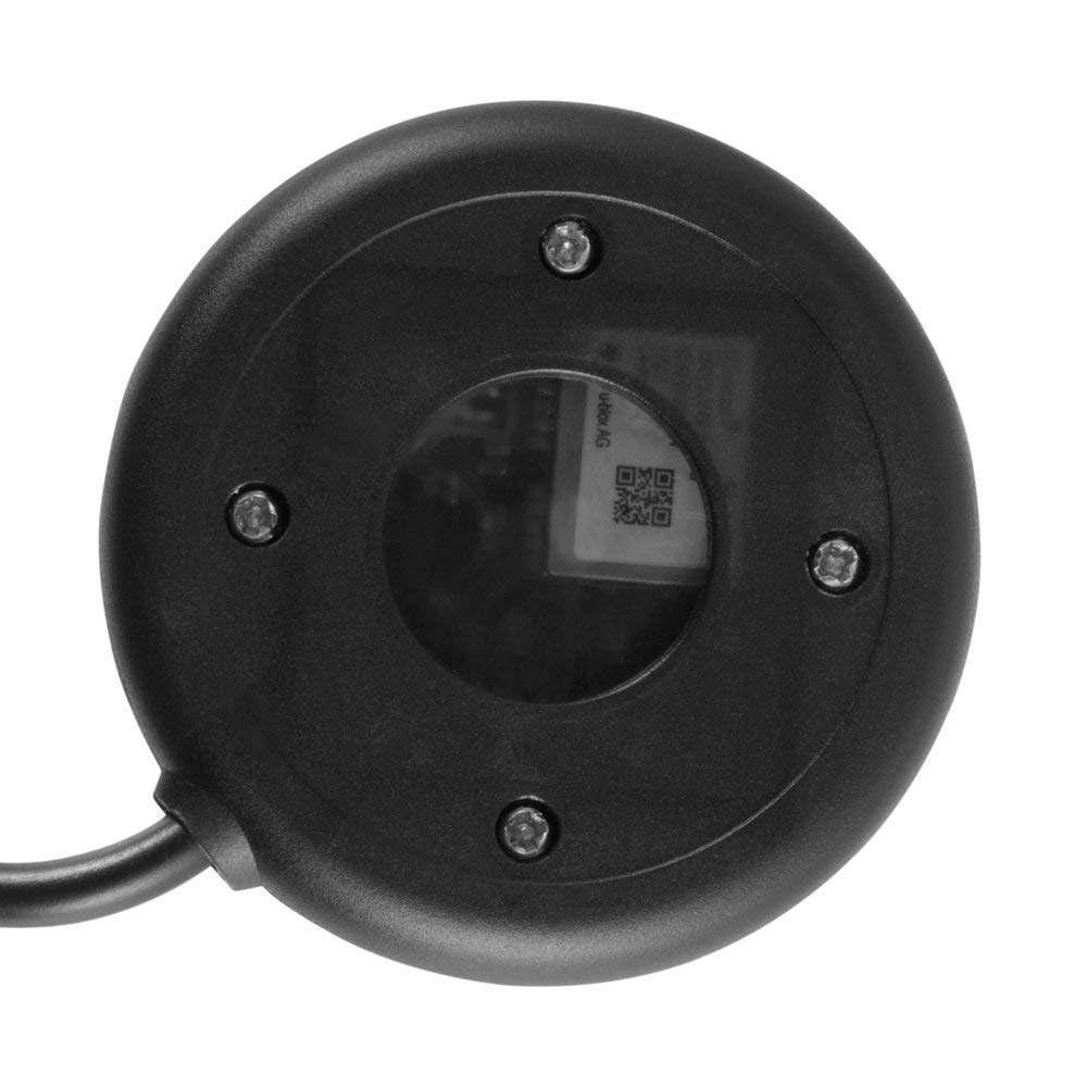
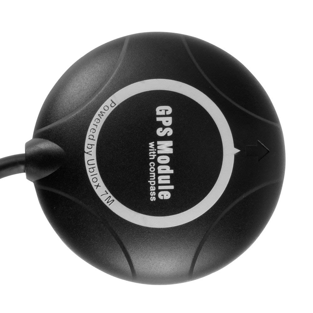
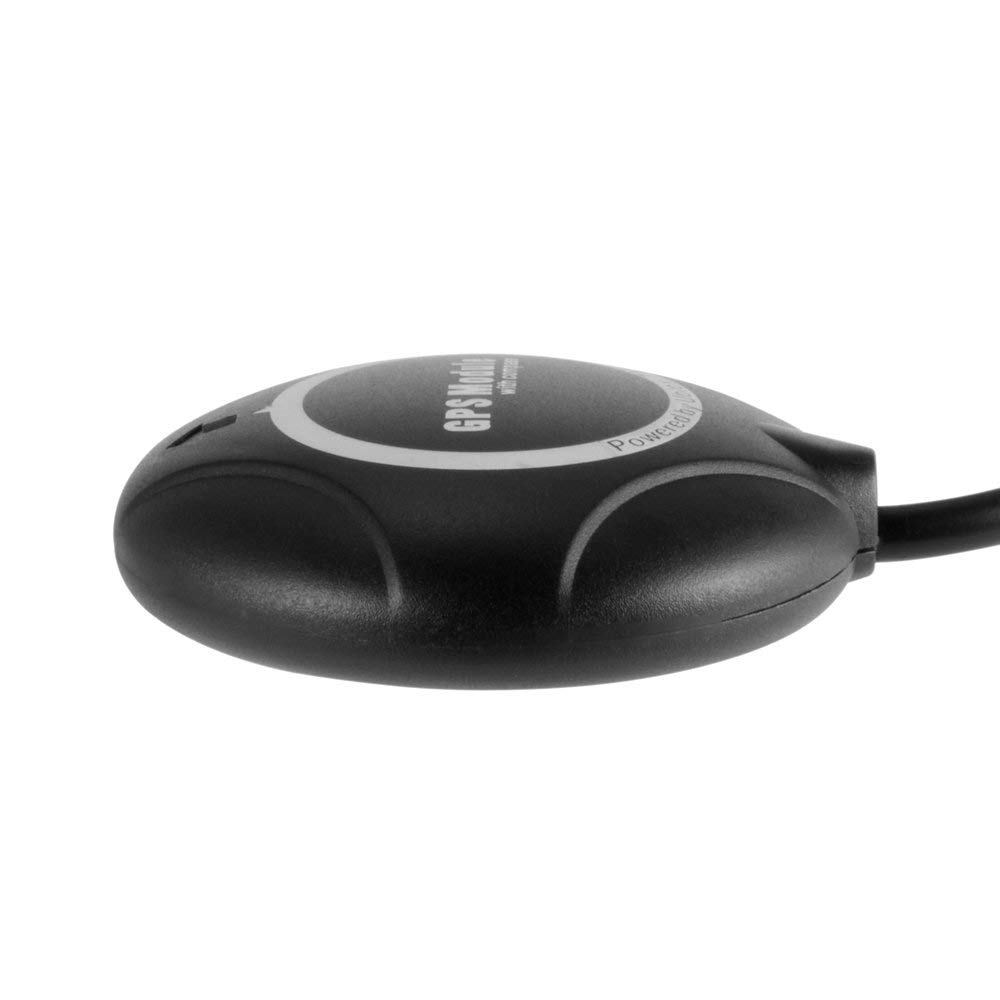
- Protective Molded Housing: Encloses the module electronics and antenna assembly in a molded plastic case.
- Compact Navigation Assembly: Combines GPS reception and compass sensing in one integrated module to simplify UAV navigation-system installation.
Technical Features & Performance Characteristics
The NEO-7M receiver processes GPS L1 satellite signals and provides positioning information to a connected flight controller. Its stated tracking sensitivity is -161dBm, while the navigation update rate is specified at up to 5Hz. The module also supports a stated acceleration limit below 4g.
The onboard HMC5883L compass provides a separate magnetic heading data source. GPS and compass information can be used together by compatible flight-control firmware for navigation functions. Actual positioning performance depends on satellite visibility, antenna placement, receiver configuration and the surrounding RF environment.
GPS, Compass & Connection Details
- GPS Connection: Connects the GPS receiver data and power lines to a compatible flight-controller GPS interface.
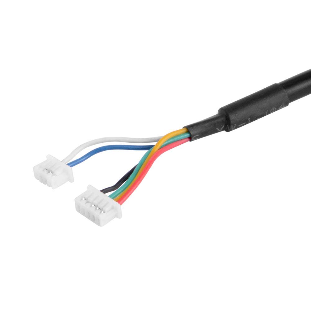
- Compass Connection: Uses the dedicated four-pin I²C compass interface for communication with a compatible flight controller.
- Six-Pin Connection: A six-pin cable arrangement is provided for compatible integrated GPS and compass installations.
- GPS Data Protocol: Supports NMEA output, including GGA, GSA and RMC sentences.
- Supply Connection: Requires a regulated DC supply within the 3.5–5.5V operating range.
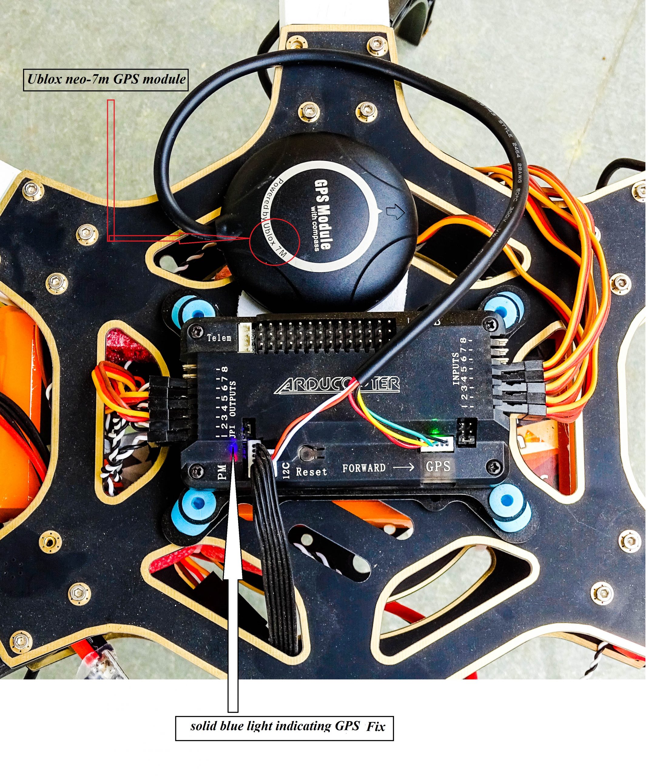
The GPS and compass interfaces must be connected to their corresponding flight-controller ports. Verify the connector pinout and interface assignments before applying power, particularly when using a flight controller with an onboard compass.
Applications
- Multirotor UAV Navigation: Supplies GPS position and compass heading data to compatible multirotor flight controllers.
- Quadcopter Position Hold: Provides positioning data for supported GPS-assisted position-hold functions.
- Return-to-Home Systems: Supplies location information used by compatible flight controllers during return-to-home operation.
- Waypoint Navigation: Supports GPS position reporting for flight controllers configured for waypoint-based navigation.
- Autonomous UAV Flight: Provides satellite positioning and heading inputs for supported autonomous flight modes.
- APM-Based Aircraft: Suitable for compatible APM flight-controller installations with correctly configured GPS and compass interfaces.
- Pixhawk-Based Platforms: Supports compatible Pixhawk navigation installations using the appropriate GPS and I²C compass connections.
- UAV Flight-Control Development: Provides GPS and compass inputs for testing and development of compatible flight-control systems.
- Navigation System Integration: Combines GPS position reporting and magnetic heading measurement in one module assembly.
- Flight-Path Monitoring: Supplies position data for compatible flight-controller logging and navigation functions.
- RC Aircraft Navigation: Can be integrated into compatible aircraft navigation systems requiring GPS positioning and compass data.
- Multirotor Research Platforms: Provides positioning and heading inputs for UAV navigation-system development and evaluation.
Package Includes
- 1 × u-blox NEO-7M GPS Module with Built-In HMC5883L Digital Compass
Product Specifications
| Parameter | Specification |
|---|---|
| Product Type | GPS Module with Integrated Digital Compass |
| GPS Receiver Model | u-blox NEO-7M |
| Main GPS Chip | u-blox NEO-7M |
| Compass Sensor | HMC5883L Digital Compass |
| Receiver Architecture | 56-channel GPS receiver |
| Satellite System | GPS |
| Receiver Frequency | L1, 1575.42MHz |
| Navigation Update Rate | Up to 5Hz |
| Tracking Sensitivity | -161dBm |
| Position Accuracy | 2–2.5m (stated range) |
| Maximum Acceleration | Less than 4g |
| Operating Voltage | 3.5–5.5V DC |
| GPS Antenna | Integrated active ceramic patch antenna |
| Compass Interface | I²C |
| GPS Data Protocol | NMEA |
| Supported NMEA Sentences | GGA, GSA and RMC |
| Default Baud Rate | 38400 bps (initial configuration) |
| Backup Power | Rechargeable backup battery |
| Configuration Retention | Onboard configuration memory |
| Housing | Molded plastic enclosure |
| Operating Temperature | -24°C to +84°C (stated range) |
| Flight-Controller Compatibility | Compatible APM and Pixhawk systems with matching interfaces and configuration |
| GPS Connection Arrangement | Dedicated GPS connection and six-pin integrated connection option |
| Compass Connection Arrangement | Four-pin I²C compass connection |
| Package Quantity | 1 module |
Connection & Operating Recommendations
- Verify Supply Voltage: Use a regulated 3.5–5.5V DC supply and confirm the flight controller’s GPS port provides a compatible voltage before connecting the module.
- Match GPS and Compass Ports: Connect the GPS data interface to the flight controller’s GPS port and the compass interface to its corresponding I²C port.
- Check Connector Pinout: Confirm power, ground, transmit, receive and I²C signal positions against the flight-controller documentation. Do not rely on connector shape alone.
- Configure the GPS Baud Rate: Match the flight controller’s GPS serial-port baud rate to the module configuration. The initial configuration is stated as 38400 bps; verify the actual configured rate before operation.
- Check Navigation Update Settings: Configure the flight controller to use a compatible GPS update rate and supported NMEA messages.
- Calibrate the Compass: Perform the flight controller’s compass calibration procedure after installation and repeat it if the module’s mounting position changes.
- Manage Internal Compass Settings: On APM 2.0 and APM 2.5 boards with an onboard compass, check the controller’s hardware and firmware requirements before connecting an external compass. Disable or isolate the internal compass only using the procedure specified for that exact board revision.
- Choose a Suitable Mounting Position: Install the GPS module away from high-current wiring, switching regulators, motors and other sources of electromagnetic interference.
- Maintain Antenna Visibility: Position the ceramic antenna with a clear view of the sky and avoid placing conductive or obstructive material directly above it.
- Allow Satellite Acquisition: After installation or relocation, allow sufficient time for the receiver to acquire satellites and establish a stable position fix before enabling GPS-dependent flight modes.
- Validate Navigation Functions: Confirm GPS lock, compass heading, position reporting and return-to-home configuration in a controlled test environment before flight.