
SPIDER Automation Micro MinimOSD Module | ATmega328P & MAX7456 Analogue FPV Telemetry Overlay
The Micro MinimOSD is a compact analogue video on-screen display module designed to combine flight-controller telemetry with a live FPV camera video signal. It uses an ATmega328P 8-bit microcontroller and a MAX7456 monochrome OSD processor to generate text and telemetry overlays for compatible analogue video systems. The module supports firmware configurations based on MAVLink and MultiWii Serial communication, allowing integration with compatible autopilot and flight-controller platforms.
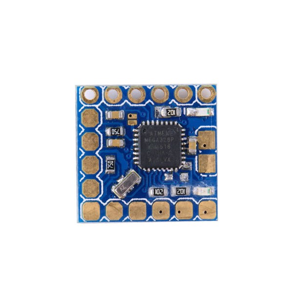
This version retains the core MinimOSD functionality in a smaller board layout with exposed connection pads for commonly used signals. It provides dual battery-voltage monitoring connections, RSSI input, an external current-sensor connection, configurable power sections and a PAL video-selection jumper. The separate power sections can be combined through solder jumpers when required by the intended electrical arrangement.
Unlike conventional MinimOSD hardware that incorporates an onboard DC/DC converter, this Micro MinimOSD version does not include that converter. It therefore requires an appropriately regulated external power arrangement compatible with the board’s power connections. Firmware programming is available through an FTDI-compatible interface, while a standard 6-pin ISP header provides an additional programming connection.
Key Features
- Compact Micro MinimOSD Design: A reduced-size OSD board layout designed for FPV installations where PCB space and accessible connection pads are important.
- ATmega328P 8-Bit Processor: Provides the microcontroller platform for processing compatible telemetry data and controlling the OSD functions.
- MAX7456 Monochrome OSD Processor: Generates monochrome text and telemetry overlays on compatible analogue video feeds.
- MAVLink Communication Support: Compatible MAVLink firmware enables integration with supported ArduPilot-based autopilot systems.
- MultiWii Serial Compatibility: Supports compatible MultiWii Serial firmware configurations used by suitable MultiWii, Baseflight and Cleanflight flight controllers.
- Dual Battery Monitoring: Two battery-voltage input connections allow compatible main-flight and FPV battery voltage information to be monitored independently.
- RSSI Monitoring Input: Dedicated pad supports compatible analogue or digital PWM receiver signal-strength inputs.
- Current Sensor Connection: Provides an external current-sensor input for compatible current-monitoring configurations.
- Independent Power Sections: Two power sections with individual LED indicators provide visual indication of their respective power states.
- Power-Combining Solder Jumpers: Configurable solder bridges allow the two power sections to be electrically combined when appropriate for the installation.
- PAL Video Configuration: Dedicated solder jumper allows selection of PAL video operation for compatible analogue video equipment.
- HSYNC and LOS Test Points: Exposed diagnostic pads provide access to horizontal synchronisation and loss-of-signal-related signals.
- FTDI-Compatible Programming: Supports firmware programming through a compatible FTDI USB-to-serial adapter.
- 6-Pin ISP Interface: Standard ISP header provides an additional in-circuit programming connection.
- No Onboard DC/DC Converter: Omits the converter found on conventional MinimOSD hardware, requiring a suitable external regulated power source.
OSD Processing & Video Overlay
The Micro MinimOSD combines the ATmega328P microcontroller with the MAX7456 monochrome OSD processor. The microcontroller handles compatible telemetry communication and OSD control, while the MAX7456 generates the character-based overlay for the analogue video display path.
When configured with compatible firmware and a supported flight controller, the module can display available flight telemetry over the FPV camera image. The actual information shown depends on the firmware build, connected flight-controller data, available sensor inputs and OSD configuration.
- Video Overlay Processing: Adds monochrome text and telemetry information to a compatible analogue video feed.
- Flight Telemetry Display: Supports display of available flight-controller information through compatible MAVLink or MultiWii Serial firmware.
- Analogue Video Configuration: Includes a PAL selection jumper for supported PAL video installations.
- Signal Diagnostics: Exposed HSYNC and LOS test points provide access to relevant video signal diagnostic connections.
Firmware & Flight Controller Compatibility
The Micro MinimOSD supports different firmware approaches depending on the flight-controller communication protocol. MAVLink-compatible firmware is intended for supported ArduPilot-based systems, while MultiWii Serial-compatible firmware is intended for suitable MultiWii, Baseflight and Cleanflight platforms.
- ArduPilot / APM Systems: MAVLink-based integration with compatible ArduPilot autopilot hardware and firmware.
- MultiWii Flight Controllers: Integration using compatible MultiWii Serial firmware.
- Baseflight Controllers: Support through compatible MultiWii Serial communication configurations.
- Cleanflight Controllers: Support where the installed firmware version and configuration provide the required serial telemetry protocol.
- Standalone Configurations: The board can be used in compatible standalone OSD arrangements when the required video, telemetry and power connections are provided.
- APM / Flip / Flip32+ Platforms: The product information identifies these controller families as intended integration platforms; actual compatibility depends on the specific board revision, firmware and wiring.
Dual Battery Voltage Monitoring
The module provides two independent battery-voltage monitoring connections. This arrangement is intended to display voltage information from two compatible power sources, such as the main flight battery and a separate FPV equipment battery. The product information describes support for battery systems up to 4S on these monitoring connections.
- Main Flight Battery Monitoring: Connection for monitoring the flight battery voltage through a compatible voltage-sensing arrangement.
- FPV Battery Monitoring: Separate connection for monitoring the battery supplying compatible FPV equipment.
- Independent Power Sections: Separate power arrangements support the intended dual-source monitoring configuration.
- Power Section Linking: Solder jumpers allow the power sections to be combined where required by the chosen wiring arrangement.
RSSI & Current Sensor Integration
The Micro MinimOSD includes dedicated connection pads for receiver signal-strength and current-sensor inputs. These interfaces allow compatible external signals to be made available to supported OSD firmware for telemetry display. The sensor type, signal range, calibration and firmware configuration must match the connected hardware.
- Analogue RSSI: Supports connection of a compatible analogue receiver signal-strength output.
- Digital PWM RSSI: Provides an input pad for compatible PWM-based RSSI signals.
- External Current Sensor: Connection point for a compatible current-sensing module.
- Firmware-Based Display: RSSI and current information can be displayed when supported by the selected firmware and correctly configured.
Programming & Configuration Interfaces
Firmware programming is supported through an FTDI-compatible interface. A compatible USB-to-serial adapter can be used to connect the OSD module to a computer for supported firmware upload and configuration workflows. The board also provides a standard 6-pin ISP header for compatible in-circuit programming hardware.
- FTDI-Compatible Header: Provides the serial programming connection for a compatible FTDI adapter.
- Arduino Bootloader: The ATmega328P is described as having an Arduino bootloader for supported programming workflows.
- 6-Pin ISP Header: Provides a separate in-circuit serial programming interface.
- Firmware Selection: Select firmware that matches the flight controller’s telemetry protocol and the intended OSD configuration.
Applications
- FPV Drone Video Systems: Telemetry overlay integration for compatible analogue FPV camera and video transmission systems.
- Multirotor Telemetry Displays: Displays available flight-controller information over the live video feed.
- ArduPilot-Based UAVs: MAVLink telemetry overlay for supported ArduPilot autopilot configurations.
- APM Flight-Control Systems: OSD integration with compatible APM-based flight controllers.
- MultiWii Flight Controllers: Video telemetry integration through supported MultiWii Serial firmware.
- Baseflight-Based Aircraft: OSD integration with compatible Baseflight serial telemetry configurations.
- Cleanflight-Based Multirotors: Telemetry display integration where the installed firmware supports the required communication protocol.
- Dual-Battery FPV Installations: Monitoring of compatible flight and FPV battery voltage sources.
- Receiver Signal Monitoring: RSSI input integration for compatible analogue or digital PWM receiver outputs.
- Current Monitoring Systems: Connection to compatible external current sensors for supported OSD telemetry.
- Analogue PAL Video Systems: OSD integration in compatible PAL video configurations.
- Standalone OSD Projects: Compact video-overlay integration where compatible telemetry and power interfaces are available.
- Flight-System Development: Integration and evaluation of telemetry display hardware in compatible UAV electronics systems.
Package Includes
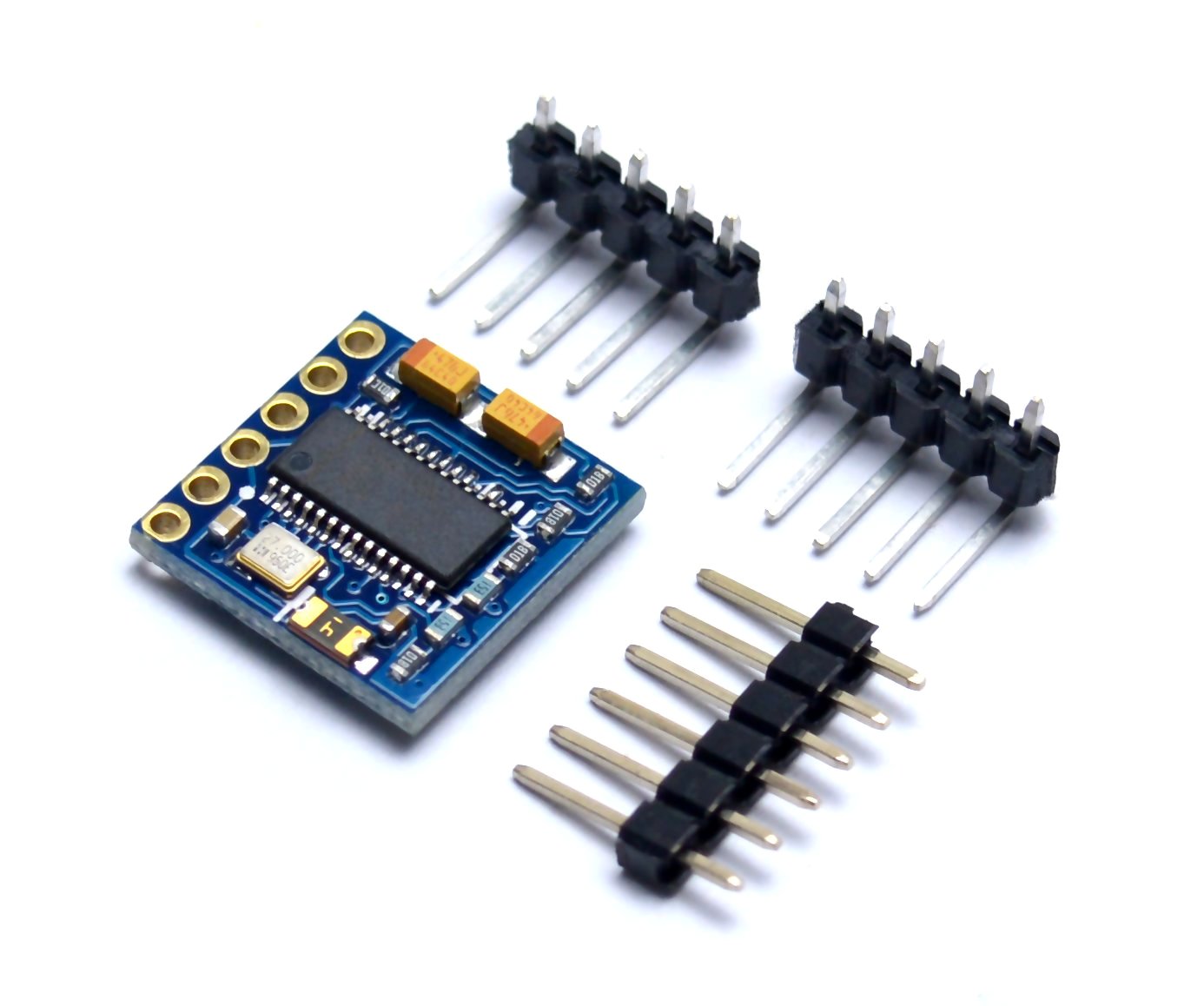
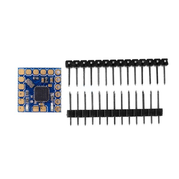
- 1 × Micro MinimOSD Module
- 1 × Straight Berg Pin Connector
- 1 × 90° Right-Angle Berg Pin Connector
Note: The supplied Berg pin connectors are not factory-soldered to the PCB. Soldering and connector orientation must be selected according to the intended installation.
Product Specifications
| Parameter | Specification |
|---|---|
| Product Name | Micro MinimOSD |
| Product Type | Analogue Video On-Screen Display Module |
| Microcontroller | ATmega328P, 8-bit AVR |
| Bootloader | Arduino bootloader |
| OSD Processor | MAX7456 |
| Display Type | Monochrome analogue video OSD |
| Firmware Compatibility | MAVLink-compatible and MultiWii Serial-compatible firmware |
| Flight Controller Compatibility | Compatible ArduPilot/APM, MultiWii, Baseflight and Cleanflight configurations |
| Battery Monitoring Inputs | 2 independent battery-voltage connections |
| Battery Monitoring Range | Up to 4S battery systems, as described in the product information |
| RSSI Input | Analogue or digital PWM signal input pad |
| Current Sensor Interface | External current-sensor connection pad |
| Power Sections | 2 independent sections with LED indicators |
| Power Configuration | Solder jumpers for combining power sections |
| PAL Configuration | PAL video-selection solder jumper |
| Diagnostic Test Points | HSYNC and LOS |
| Programming Interface | FTDI-compatible interface |
| ISP Interface | Standard 6-pin ISP header |
| Onboard DC/DC Converter | Not included |
| Current Consumption | 500mA (published specification; verify before power-system design) |
| Operating Temperature | −40°C to +85°C |
| Length | 16mm |
| Width | 15.6mm |
| Height | 4mm |
| Product Weight | 4g |
Connection & Operating Recommendations
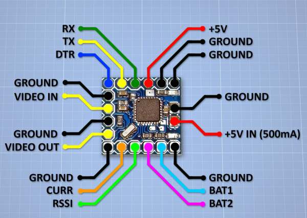
- Provide Regulated External Power: This Micro MinimOSD version does not include an onboard DC/DC converter. Use a suitable regulated supply compatible with the board’s power-input arrangement and verify the required voltage from the board pinout before connection.
- Verify the Power-Section Arrangement: Identify the two power sections and their LED indicators before wiring. Configure the solder jumpers only after confirming whether the installation requires separate or combined power sections.
- Check Battery Voltage-Sense Wiring: Connect the main-flight and FPV battery monitoring inputs according to the board pinout and supported voltage-sensing range. Do not treat a voltage-sense input as a power-supply input.
- Confirm Video Standard: Match the OSD configuration and PAL selection jumper to the connected camera and video system. Verify the required video format before final installation.
- Match Firmware to the Flight Controller: Select MAVLink or MultiWii Serial firmware according to the flight controller’s supported telemetry protocol and firmware configuration.
- Use a Compatible FTDI Adapter: Check the FTDI header pinout and voltage compatibility before connecting a USB-to-serial programming adapter.
- Verify RSSI Signal Type: Confirm whether the receiver provides analogue RSSI or PWM RSSI and configure the OSD firmware accordingly.
- Calibrate the Current Sensor: Use a compatible current sensor and configure its scaling and calibration values in the supported firmware before relying on displayed current readings.
- Solder Headers Carefully: Install the straight or right-angle Berg connector according to the intended mounting arrangement, taking care to avoid solder bridges between adjacent pads.
- Inspect Video and Telemetry Connections: Check video input/output wiring, telemetry signal connections, power polarity and ground continuity before applying power to the complete FPV system.