
SPIDER Automation Active GPS/GLONASS GNSS Patch Antenna | 3-Metre Cable, Magnetic Mount & SMA Interface
Description
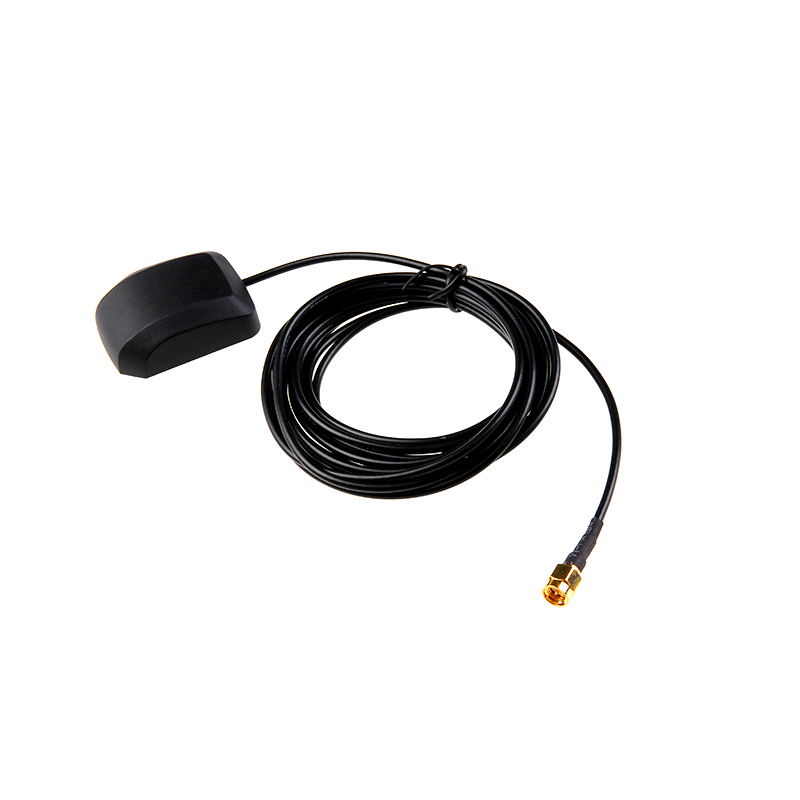
The SPIDER Automation Active GPS/GLONASS GNSS Patch Antenna is an external satellite-navigation antenna assembly designed for compatible GNSS receivers used in positioning, navigation and embedded electronics applications. It combines a patch antenna element with an integrated preamplifier to receive satellite RF signals and amplify them before delivery to the connected receiver.
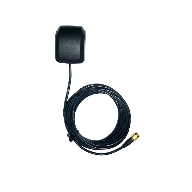
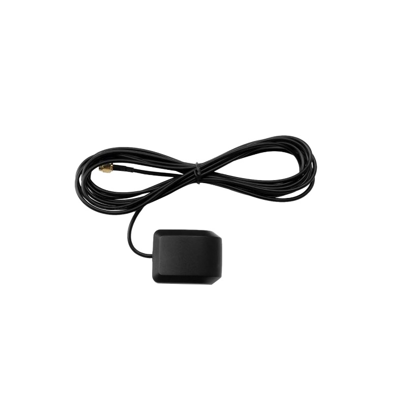
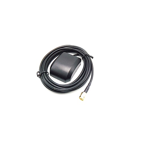
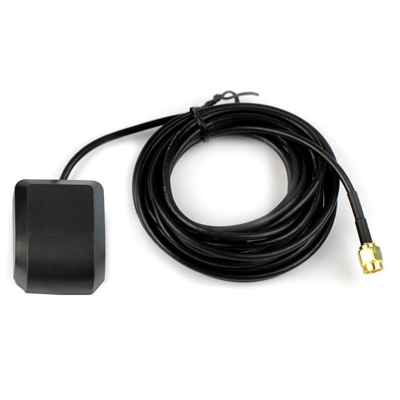
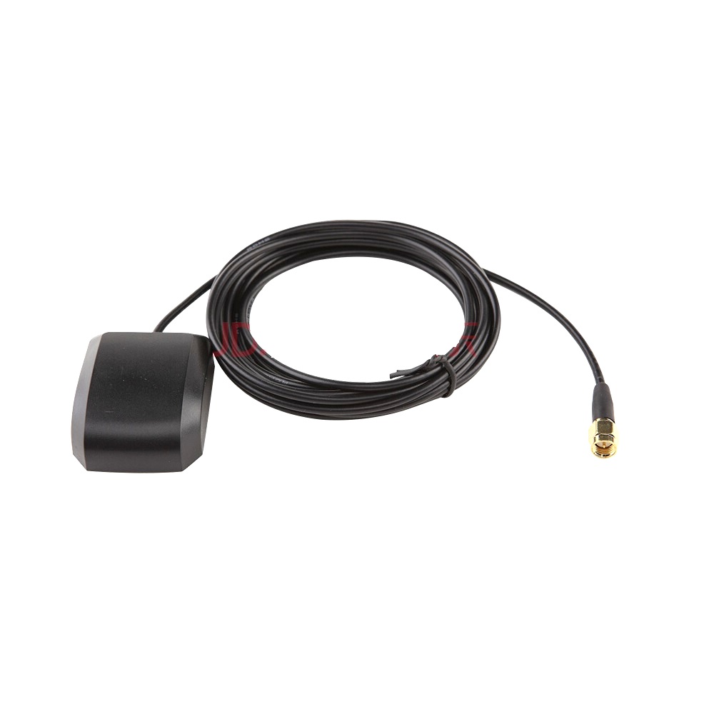
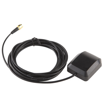
The antenna is supplied with a 3-metre cable and SMA male connector, allowing flexible placement relative to the GNSS receiver. Its magnetic base provides convenient temporary mounting on metallic surfaces, while double-sided adhesive tape can be used for attachment to other suitable surfaces. The compact antenna assembly is suitable for installations where the receiver electronics and antenna need to be positioned separately.
An IP67-rated, UV-resistant enclosure supports outdoor installation. The integrated preamplifier requires a 3–7V DC supply through the RF connection, with a maximum operating current of 15mA. The antenna is designed for compatible GPS/GLONASS receiver systems, including suitable Raspberry Pi GNSS HAT and Arduino GNSS shield configurations.
Key Features
- GPS/GLONASS GNSS Reception: Designed for satellite navigation applications using compatible GPS and GLONASS receiver systems.
- Patch Antenna Construction: Uses a patch antenna element for receiving satellite navigation signals.
- Integrated Preamplifier: Amplifies received RF signals before they travel to the connected receiver.
- 3-Metre Cable: Provides installation flexibility and allows the antenna to be positioned away from the host electronics.
- SMA Male RF Connector: Provides a standardised coaxial connection for compatible receiver antenna ports.
- Magnetic Mounting Base: Supports convenient temporary installation on suitable metallic surfaces.
- Double-Sided Adhesive Mounting: Allows attachment to compatible non-metallic or metallic surfaces using suitable adhesive tape.
- IP67 Enclosure Protection: Designed to resist dust ingress and temporary water immersion under the specified IP67 test conditions.
- UV-Resistant Housing: Supports outdoor use in installations exposed to sunlight.
- 50Ω RF Interface: Matches the nominal impedance of compatible GNSS antenna input systems.
- Low-Noise Preamplifier: Features a typical noise figure of 1.5dB.
- Low-Voltage Operation: Requires a 3–7V DC supply for the integrated preamplifier.
Technical Features & Performance Characteristics
- Active Antenna Architecture: The integrated preamplifier amplifies the received satellite signal within the antenna assembly before transmission through the coaxial cable.
- RF Signal and Power Path: The preamplifier receives its DC operating supply through the same RF connection used to carry the antenna signal to the receiver.
- Typical Noise Figure: The preamplifier has a typical noise figure of 1.5dB.
- RF Impedance: The antenna assembly uses a nominal 50Ω impedance for compatible RF connections.
- Supply Requirement: The preamplifier operates from a 3–7V DC supply, with a maximum operating current of 15mA.
- Extended Cable Placement: The 3-metre cable supports remote antenna positioning to help obtain a more suitable satellite reception location.
Mounting & Enclosure Design
- Magnetic Base: The integrated magnet allows the antenna to remain positioned on suitable ferromagnetic metal surfaces.
- Adhesive Attachment: Double-sided adhesive tape can be used to secure the antenna to a clean, compatible mounting surface.
- Compact Antenna Assembly: The small enclosure supports installations with limited mounting space.
- Outdoor Enclosure: The IP67-rated housing is designed for protection against dust and temporary water immersion.
- UV Resistance: The enclosure is designed to withstand outdoor sunlight exposure.
Applications
- Raspberry Pi GNSS Projects: External antenna connection for compatible Raspberry Pi GPS/GNSS HATs with suitable SMA input and antenna-bias support.
- Arduino GNSS Systems: External satellite antenna installation for compatible Arduino GNSS shields and receiver modules.
- GPS Navigation Equipment: Satellite signal reception for compatible GPS navigation devices.
- GLONASS Navigation Systems: External antenna installation for compatible GLONASS-enabled receivers.
- Embedded Positioning Systems: Antenna integration in embedded electronics requiring external GNSS reception.
- UAV Navigation Electronics: External GNSS antenna installation in compatible unmanned aircraft navigation systems.
- Vehicle Tracking Equipment: Satellite antenna installation for compatible vehicle tracking and positioning terminals.
- Mobile Robotics: GNSS signal reception for outdoor mobile robot navigation systems.
- Outdoor Monitoring Systems: External GNSS antenna installation for compatible remote monitoring equipment.
- GNSS Development Platforms: Antenna integration during development and testing of compatible satellite positioning systems.
- Remote Receiver Installations: Positioning the antenna away from the receiver electronics using the supplied 3-metre cable.
Package Includes
- 1 × Active GPS/GLONASS GNSS Patch Antenna with 3-Metre Cable and SMA Male Connector
Product Specifications
| Parameter | Specification |
|---|---|
| Product Type | Active GNSS Antenna |
| Antenna Technology | Patch Antenna |
| Satellite Navigation Systems | GPS and GLONASS |
| Antenna Configuration | Antenna Element with Integrated Preamplifier |
| Typical Noise Figure | 1.5dB |
| Operating Voltage | 3–7V DC |
| Maximum Operating Current | 15mA |
| RF Impedance | 50Ω |
| RF Connector | SMA Male |
| Cable Length | 3 metres |
| Mounting Type | Magnetic Base and Adhesive Mounting Option |
| Enclosure Protection | IP67 |
| UV Resistance | UV-Resistant Enclosure |
| Enclosure Colour | Black |
| Product Weight | 60g |
| Package Quantity | 1 Antenna Assembly |
Connection & Operating Recommendations
- Receiver Compatibility: Confirm that the GNSS receiver supports GPS/GLONASS reception, has a compatible SMA female antenna connector and can supply the required antenna-bias voltage.
- Power Through RF Connection: The integrated preamplifier requires 3–7V DC through the RF signal path. Use a receiver with a compatible active-antenna bias output or an appropriate external bias-tee arrangement.
- Current Capacity: Ensure the antenna-bias supply can provide up to 15mA within the specified operating voltage range.
- Connector Compatibility: Check the receiver connector type and centre-contact configuration before connection. Do not force an incompatible coaxial connector.
- Antenna Placement: Position the antenna with a clear view of the sky and away from obstructions where practical. Indoor placement behind walls or beneath roofs can substantially reduce satellite signal reception.
- Outdoor Installation: Use the magnetic base on a suitable metallic surface or secure the enclosure with compatible double-sided adhesive tape.
- Cable Routing: Route the 3-metre cable without sharp bends, crushing or excessive mechanical tension. Keep it away from strong electrical noise sources where practical.
- RF Connection: Keep the SMA connection clean and properly secured to maintain reliable RF contact.
- Power Sequencing: Follow the receiver manufacturer’s instructions for antenna-bias activation and connection. Avoid applying voltage to an RF input that does not support active-antenna power.
- Reception Verification: Check the receiver’s satellite detection and signal-status information after installation to confirm that the antenna is operating correctly.