


SPIDER Automation Flip32 OMNIBUS F4 Flight Controller | STM32F405, MPU6000 SPI IMU & Integrated OSD for FPV Racing Drones
Description
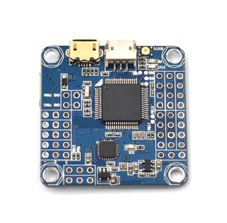
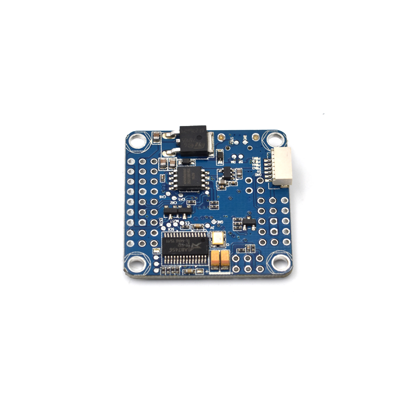
The Flip32 OMNIBUS F4 Flight Controller is an integrated flight-control and OSD board designed for FPV racing multirotors and compatible UAV platforms. Based on the STM32F405 32-bit microcontroller, it combines inertial sensing, video telemetry display, receiver interfaces, PWM outputs and onboard voltage regulation in a compact PCB layout. Its integrated architecture reduces the need for separate flight-control and OSD modules in compatible FPV builds.
The board uses an MPU6000 six-axis inertial sensor connected through SPI, incorporating a 3-axis gyroscope and 3-axis accelerometer for motion measurement. Its integrated OSD uses an AB7456/MAX7456-compatible display architecture, allowing supported flight information to be overlaid onto the FPV video feed. OSD settings can be managed through compatible Betaflight firmware and configuration tools.
For aircraft connectivity, the Flip32 OMNIBUS F4 provides six PWM outputs and supports SBUS, PPM, DSM, DSM2 and DSMX receiver connections through the designated interfaces. It also incorporates a 5V, 1.5A onboard regulator, buzzer and LED-strip ports, and 128Mbit flash memory. Its 36 × 36mm board size and 30.5 × 30.5mm mounting-hole pattern support installation in compatible multirotor frames.
Key Features
- STM32F405 MCU: Uses an F405 32-bit microcontroller for executing compatible flight-control firmware and processing aircraft-control information.
- MPU6000 SPI IMU: Integrates a gyroscope and accelerometer for aircraft angular-motion and acceleration measurements.
- Integrated OSD Chip: Uses an AB7456/MAX7456-compatible OSD architecture for displaying supported telemetry over the FPV video signal.
- 128Mbit Flash Memory: Provides 16MB of onboard flash storage for supported firmware and data functions.
- Six PWM Output Channels: Provides six pin-header output connections for compatible ESC and servo-control applications.
- SBUS and PPM Inputs: Supports compatible receiver signal connections through designated pin headers.
- DSM Receiver Interface: Provides a dedicated plug connection for compatible DSM, DSM2 and DSMX receiver systems.
- Integrated Voltage Regulator: Includes an onboard 5V, 1.5A regulator stage for the board’s supported power requirements.
- Buzzer Port: Provides a connection for a compatible audible flight-status indicator.
- LED-Strip Port: Supports connection of a compatible addressable LED strip through the designated interface.
- DShot Compatibility: Supports DShot ESC control with the appropriate Betaflight firmware target and configuration.
- Through-Hole Pin-Header Design: Uses through-hole pin-header connections rather than SH-series peripheral connectors for the specified interfaces.
- Compact Flight-Controller Layout: Uses a 30.5 × 30.5mm mounting pattern on a 36 × 36mm PCB.
Flight-Control Processing & Inertial Measurement
The STM32F405 microcontroller serves as the primary processing unit of the Flip32 OMNIBUS F4. It executes the installed flight-control firmware and processes receiver commands, inertial sensor measurements and configured output signals.
The onboard MPU6000 inertial measurement unit combines a 3-axis gyroscope and 3-axis accelerometer. The gyroscope measures angular velocity, while the accelerometer measures linear acceleration. These measurements provide the flight-control firmware with motion data used for aircraft attitude estimation and stabilization.
The MPU6000 communicates with the processor through the SPI interface. This digital sensor connection forms part of the board’s integrated flight-control architecture and supports the sensor-processing requirements of compatible firmware.
Integrated OSD & FPV Video Telemetry
The Flip32 OMNIBUS F4 incorporates an AB7456/MAX7456-compatible OSD chip connected to the main flight-control processor. This integration allows supported flight information to be overlaid onto the FPV video feed without requiring a separate external OSD module.
With compatible Betaflight firmware and configuration software, available OSD elements can be configured through the flight-controller setup interface. The integrated design simplifies telemetry configuration by combining the flight-control and OSD functions on the same board.
Receiver Connectivity & PWM Outputs
The flight controller supports multiple receiver connection formats for integration with compatible RC radio systems. SBUS and PPM receiver inputs are provided through pin headers, while DSM-family receiver connections use the designated plug interface.
- SBUS: Supported through the designated receiver pin-header connection.
- PPM: Supported through the designated receiver pin-header connection and compatible firmware configuration.
- DSM: Supported through the specified receiver plug.
- DSM2: Supported through the specified receiver plug.
- DSMX: Supported through the specified receiver plug.
- PWM Outputs: Six output channels are provided through pin-header connections for compatible ESC and servo-control equipment.
Receiver protocol selection, signal assignment and output configuration must match the connected receiver, installed firmware and board connection layout. Confirm the pinout before wiring.
Onboard Voltage Regulation & Power Management
The Flip32 OMNIBUS F4 incorporates an onboard 5V voltage regulator rated at 1.5A. The product design describes direct LiPo battery input through the board’s designated power connection, with the onboard regulator providing the lower-voltage supply required by the flight controller and compatible equipment.
The regulator’s 1.5A rating represents its specified output-current capacity. The actual available current for external peripherals depends on the total load, thermal conditions and board power design. Verify the designated battery-input connection and supported battery-cell range against the exact hardware revision before applying flight-battery voltage.
Buzzer, LED Strip & ESC Protocol Support
Dedicated buzzer and LED-strip ports provide additional integration options for compatible flight-status indicators and lighting accessories. The buzzer connection can be used with a compatible audible indicator, while the LED-strip port supports an appropriate addressable LED accessory when enabled by the firmware.
The board also supports DShot ESC control when configured with a compatible Betaflight firmware target. The supplied product information identifies the AirbotF4 target for the specified Betaflight 3.1 DShot configuration. Verify firmware-target compatibility and output assignments before connecting ESCs.
Firmware & Configuration Support
- Betaflight: Supports compatible Betaflight firmware, with the product specification identifying version 3.1.7_OMNIBUSF4SD.
- Betaflight Configurator: Used for compatible firmware flashing, flight-controller configuration, receiver setup and OSD adjustment.
- Raceflight: Listed as a supported flight-control firmware platform for compatible board configurations.
- Raceflight CC3D REVO Firmware: Identified in the product feature information as a supported firmware option.
- DShot Configuration: Requires the appropriate Betaflight firmware target and configuration for the board.
Applications
- FPV Racing Drones: Provides integrated flight-control processing, inertial sensing and OSD functions for compatible racing multirotors.
- FPV Freestyle Multirotors: Supports configurable flight stabilization and telemetry display for freestyle drone builds.
- Custom Quadcopter Builds: Provides a flight-control platform for compatible four-motor aircraft configurations.
- Multirotor UAV Development: Suitable for compatible UAV development and flight-control integration projects.
- Betaflight-Based Drone Systems: Supports multirotor builds using compatible Betaflight firmware and configuration tools.
- Raceflight-Based Aircraft: Supports compatible flight-control configurations using the listed Raceflight firmware platform.
- Analogue FPV Video Systems: Integrated OSD architecture supports telemetry overlay in compatible FPV video chains.
- Flight Telemetry Display: Provides supported flight information through the onboard OSD for viewing on FPV goggles or monitors.
- SBUS Receiver Integration: Supports compatible radio receivers providing SBUS output.
- PPM Receiver Integration: Supports compatible radio receivers providing PPM output.
- DSM Receiver Integration: Provides a designated connection for compatible DSM-family receiver systems.
- PWM ESC Control: Provides six PWM outputs for compatible electronic speed controllers and other supported devices.
- DShot ESC Systems: Supports compatible DShot-based ESC control when the required firmware target and settings are used.
- Flight-Status Indication: Supports integration of compatible buzzer and LED-strip accessories.
- Compact Flight-Control Assemblies: Combines processor, IMU, OSD, power regulation and receiver interfaces in one board.
Package Includes
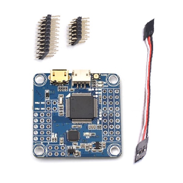
- 1 × Flip32 OMNIBUS F4 Flight Controller
- 1 × Connecting Cable
- 1 × 3 × 10 Straight Header Pins
- 1 × 2 × 5 Straight Header Pins
Product Specifications
| Parameter | Specification |
|---|---|
| Product Type | Flight Controller with Integrated OSD |
| Model | Flip32 OMNIBUS F4 |
| Main Processor | STM32F405 MCU |
| Motion Sensor | MPU6000 |
| Sensor Interface | SPI |
| Sensor Functions | 3-Axis Gyroscope and 3-Axis Accelerometer |
| OSD Chip | AB7456 / MAX7456-Compatible Architecture |
| OSD | Integrated On-Screen Display |
| Onboard Flash Memory | 128Mbit (16MB) |
| MicroSD Card Slot | No |
| Receiver Input Support | SBUS, PPM, DSM, DSM2 and DSMX |
| Receiver Connections | Pin Headers for SBUS/PPM; Designated Plug for DSM-Family Receivers |
| PWM Outputs | 6 Channels |
| PWM Output Connection | Pin Headers |
| Voltage Regulator | Integrated 5V Regulator |
| Regulator Output Voltage | 5V DC |
| Regulator Output Current Rating | 1.5A |
| Specified Input Voltage | 5V DC |
| Firmware | Betaflight 3.1.7_OMNIBUSF4SD |
| Additional Firmware Support | Raceflight / Raceflight CC3D REVO Firmware |
| ESC Protocol Support | DShot with Compatible Betaflight Firmware Configuration |
| Additional Ports | Buzzer Port and LED-Strip Port |
| PCB Connection Design | Through-Hole Pin-Header Design for Specified Connections |
| Board Length | 36mm |
| Board Width | 36mm |
| Board Height | 7mm |
| Mounting Hole Pattern | 30.5 × 30.5mm |
Connection & Operating Recommendations
- Verify Battery Input Compatibility: The product description claims direct LiPo input and mentions operation with batteries up to 5S, while the specification table identifies 5V DC input. Confirm the exact board revision, battery-input pads and supported voltage range before connecting a LiPo battery directly.
- Observe Regulator Capacity: The onboard regulator is rated at 5V, 1.5A. Keep the combined load of the flight controller, receiver and connected peripherals within the available output capacity.
- Check Receiver Pinout: Verify signal, power and ground positions before connecting SBUS, PPM or DSM-family receivers. Use the appropriate designated connector.
- Configure Receiver Protocol: Select the matching receiver protocol in the installed firmware and verify that receiver input is detected before flight operation.
- Verify PWM Channel Assignment: Confirm the six PWM output assignments and signal orientation before connecting ESCs or servo equipment.
- Use Compatible DShot Firmware: Confirm the required Betaflight target and firmware version before enabling DShot ESC control.
- Check OSD Video Connections: Verify the FPV camera video input, video output and ground wiring against the board connection documentation.
- Connect Buzzer and LED Accessories Correctly: Check the port pinout and electrical requirements of compatible buzzer and LED-strip accessories before installation.
- Inspect Soldering: Examine all through-hole header joints and power connections for solder bridges, loose joints and accidental shorts before powering the board.
- Confirm Mounting Alignment: Use the 30.5 × 30.5mm mounting pattern and ensure that mounting hardware does not contact exposed PCB components or solder joints.
- Validate Firmware Configuration: Check sensor detection, receiver response, OSD operation and ESC output configuration after firmware installation and before flight testing.