
SPIDER Automation | FPCA1T254-16 16-Pin FFC/FPC Adapter Board | 1.0mm to 2.54mm PCB Interconnection
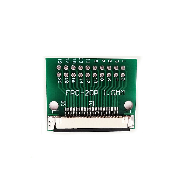
The FPCA1T254-16 FFC/FPC Adapter Board is a 16-position interconnection board designed to interface a compatible 1.0mm-pitch flexible flat cable (FFC) or flexible printed circuit (FPC) with a PCB connection arrangement using 2.54mm × 2.54mm through-hole spacing. It addresses the integration requirement that arises when a compact flexible-cable assembly must connect to a circuit board with a wider terminal-spacing layout.
The adapter accommodates a 16-contact cable interface, allowing multiple electrical paths to be brought into a single PCB connection area. This is useful in display assemblies and other electronic modules where flexible cables provide compact interconnection between separate circuit sections. The FPCA1T254-16 functions as a passive connection interface: it adapts the physical connection arrangement without performing signal amplification, voltage conversion or communication-protocol processing.
Product Overview & Interface Design
The adapter brings together two different connection-spacing requirements. The cable-facing interface is designed for a 1.0mm FFC/FPC pitch, while the PCB-side arrangement uses 2.54mm × 2.54mm through-hole spacing. This spacing transition allows a compatible fine-pitch flexible cable to be incorporated into an electronic assembly designed around more widely spaced PCB connection points.
Its 16-position configuration is intended for flexible-cable assemblies with sixteen corresponding contacts. This makes the adapter relevant to display and module interconnections where several signals need to pass between circuit sections through one cable. The cable’s conductor count, pitch, width, exposed-contact orientation and insertion geometry must all match the adapter interface; pin count and pitch alone do not establish complete compatibility.
Technical Features & Integration Benefits
- 16-Position Connection: Accommodates a 16-contact flexible-cable interface, supporting multiple electrical connections through one adapter.
- 1.0mm Fine-Pitch Interface: Supports compatible FFC/FPC cables with closely spaced contacts used in compact electronic modules.
- 2.54mm × 2.54mm PCB Spacing: Provides a wider through-hole connection arrangement for integration with conventional PCB layouts.
- Passive Pitch Adaptation: Bridges the physical connection spacing between the flexible cable and PCB without adding electronic signal-processing functionality.
- Display Connection Support: Provides an interface for terminating compatible display-module flexible cables to a separate circuit board.
- Board-Level Interconnection: Helps connect flexible-cable-equipped modules to circuit boards with a different connection-spacing arrangement.
- Corrosion-Resistance Feature: Identified with high corrosion resistance as a product feature; no specific contact finish or corrosion-test classification is defined.
- Lightweight Construction: Has an approximate product weight of 4g, supporting use in compact electronic assemblies.
Electrical Interface & PCB Integration
The FPCA1T254-16 provides a 16-position connection path between the FFC/FPC cable and the PCB-side terminals. The flexible cable must have the correct 16-conductor arrangement and 1.0mm contact pitch. Cable width, thickness, contact exposure and orientation must also be checked against the physical connector interface to ensure correct engagement.
For PCB integration, the specified 2.54mm × 2.54mm through-hole spacing should be used when checking the receiving board layout. Verify the actual terminal arrangement and pin mapping before preparing the footprint or connecting the adapter to the circuit. The adapter does not define a universal signal assignment, so the sixteen connections must be mapped according to the connected module and circuit schematic.
Applications
The FPCA1T254-16 is intended for electronic assemblies that require a 16-position flexible-cable interface to connect with a PCB layout using wider through-hole spacing. Relevant integration applications include:
- Display Module Termination: Connecting compatible 16-contact display FFC/FPC cables to display controller or interface boards.
- Embedded Display Systems: Routing display signals between a compact panel assembly and its associated processing PCB.
- Electronic Control Boards: Adapting flexible-cable module connections to a circuit board designed around 2.54mm through-hole spacing.
- Communication Equipment: Interconnecting compatible internal electronic modules through multi-conductor flexible cables.
- Automotive Electronics: Supporting suitable flexible-cable connections in compact automotive electronic assemblies.
- Consumer Electronic Equipment: Connecting internal display or interface modules where flexible-cable routing is used.
- Medical Electronic Instruments: Providing a compact cable-to-board interface in compatible instrument electronics.
- Instrumentation Assemblies: Connecting display, interface or control sections to a main PCB through a 16-position flexible cable.
- Electronic Prototyping: Evaluating compatible FFC/FPC module connections with a PCB layout that uses 2.54mm-spaced through-hole terminals.
- Equipment Servicing: Replacing an existing adapter in an assembly where the cable interface, connection arrangement and PCB layout match.
Package Includes
- 1 × FPCA1T254-16 16-Pin FFC/FPC Adapter Board, 1.0mm to 2.54mm
Product Specifications
| Parameter | Specification |
|---|---|
| Model Number | FPCA1T254-16 |
| Product Type | FFC/FPC Adapter Board |
| Number of Pins | 16 |
| Cable Interface | FFC/FPC |
| FFC/FPC Pitch | 1.0mm |
| PCB-Side Spacing | 2.54mm × 2.54mm |
| PCB Connection Arrangement | Through-hole spacing |
| Adapter Function | 1.0mm FFC/FPC interface to 2.54mm × 2.54mm PCB connection spacing |
| Corrosion Resistance | High corrosion resistance |
| Product Weight | Approximately 4g |
| Package Quantity | 1 piece |
| Package Contents | 1 × 16-pin FFC/FPC adapter board |
Connection & Operating Recommendations
- Confirm Cable Configuration: Use a compatible 16-conductor FFC/FPC cable with 1.0mm contact pitch. Check the cable width, thickness and exposed-contact arrangement before installation.
- Check Contact Orientation: Verify the exposed-contact side and insertion direction against the adapter’s physical interface. Do not assume all flexible cables use the same contact orientation.
- Verify PCB Spacing: Check the receiving PCB against the specified 2.54mm × 2.54mm through-hole spacing and confirm the actual terminal arrangement before board preparation.
- Match Pin Assignments: Verify all sixteen connections against the circuit schematic or module documentation. Do not rely on pin order alone when replacing an existing connection.
- Use Controlled Soldering: Apply a suitable soldering process for the PCB and terminals. Avoid excessive heat or mechanical force that could damage the adapter or circuit board.
- Maintain Cable Alignment: Ensure the flexible cable is correctly aligned during connection and avoid twisting, sharp folds or lateral force near the interface.
- Provide Cable Support: Route and secure the cable so that vibration, movement or cable tension does not place continuous mechanical stress on the connection.
- Inspect Before Power-Up: Check solder joints, cable seating, contact alignment and pin-to-pin continuity before energising the connected electronics.