
SPIDER Automation | FPCA1T254-12 12-Pin FFC/FPC Adapter Board | 1.0mm to 2.54mm PCB Interconnection
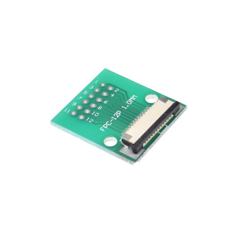
The FPCA1T254-12 FFC/FPC Adapter Board is a 12-position interconnection board designed to interface a compatible 1.0mm-pitch flexible flat cable (FFC) or flexible printed circuit (FPC) with a PCB connection arrangement using 2.54mm × 2.54mm through-hole spacing. It addresses the practical requirement of connecting compact, fine-pitch flexible-cable assemblies to electronic boards designed around a wider terminal spacing.
Flexible cables are commonly used to connect display modules and other compact electronic assemblies to their associated circuit boards. The FPCA1T254-12 provides an intermediate connection format for a 12-conductor interface, allowing the cable-side contact pitch and PCB-side connection spacing to differ. Its model-specific configuration makes it important to match the cable conductor count, 1.0mm pitch, contact orientation and PCB connection layout before integration.
Product Overview & Interface Design
The adapter is configured around two distinct connection-spacing requirements. The flexible-cable interface uses a 1.0mm pitch, while the PCB-side connection arrangement uses 2.54mm × 2.54mm through-hole spacing. This allows a compatible fine-pitch FFC/FPC assembly to be brought into a circuit-board layout with more widely spaced connection points.
The 12-pin configuration accommodates a 12-position cable interface, making it suitable for assemblies that need multiple conductors routed through one compact flexible-cable connection. The adapter functions as a passive interconnection component: it provides the physical and electrical connection path between the cable interface and PCB connection points, rather than changing signal levels, processing data or converting communication protocols.
Technical Features & Integration Benefits
- 12-Position Connection: Provides twelve connection positions for compatible FFC/FPC cable assemblies, supporting multi-conductor electronic interconnection.
- Fine-Pitch Cable Interface: The 1.0mm contact pitch accommodates compatible flexible cables used in compact display and electronic modules.
- Wider PCB Connection Spacing: The 2.54mm × 2.54mm through-hole arrangement supports integration with circuit-board layouts using conventional connection spacing.
- Passive Pitch Adaptation: Bridges the cable-side and PCB-side connection arrangements without adding signal-processing or voltage-conversion functionality.
- Display Connection Support: Provides an interface for terminating compatible display-module flexible cables to a separate PCB.
- Board-Level Interconnection: Helps connect electronic modules that use flexible cables but require a different PCB connection layout.
- Corrosion-Resistance Feature: Identified with high corrosion resistance as a product feature; the specific contact finish and corrosion-test classification are not defined.
- Compact Component Format: The adapter weighs approximately 3g, making it a lightweight interconnection component for electronic assemblies.
Electrical Interface & PCB Integration
The adapter provides a 12-position connection path between the FFC/FPC cable and the PCB-side terminals. Cable selection should be based on the actual 12-conductor count and 1.0mm pitch, along with the cable width, thickness, exposed-contact orientation and insertion geometry. A matching pitch by itself does not guarantee mechanical or electrical compatibility.
On the PCB side, the specified 2.54mm × 2.54mm through-hole spacing should be used when checking the receiving board layout. Confirm the physical terminal arrangement and electrical pin mapping before finalising the footprint or connecting the adapter to a circuit. The adapter does not establish a universal pin assignment; signal order must be matched to the connected module and PCB design.
Applications
The FPCA1T254-12 is intended for electronic assemblies that require a 12-position flexible-cable interface to connect with a PCB layout using wider through-hole spacing. Typical integration areas include:
- Display Module Termination: Connecting compatible 12-contact display FFC/FPC cables to a separate display controller or interface board.
- Embedded Display Systems: Routing display signals between a compact panel assembly and its associated processing PCB.
- Electronic Control Boards: Adapting flexible-cable module connections to a circuit board designed around 2.54mm through-hole spacing.
- Communication Equipment: Interconnecting compatible internal modules through a multi-conductor flexible cable.
- Automotive Electronics: Supporting suitable internal flexible-cable connections in compact electronic assemblies.
- Consumer Electronic Equipment: Connecting internal display or interface modules where flexible cable routing is used.
- Medical Electronic Instruments: Providing a compact cable-to-board interface in compatible instrument electronics.
- Instrumentation Assemblies: Connecting display or interface sections to a main PCB through a 12-position flexible cable.
- Electronic Prototyping: Evaluating compatible FFC/FPC module connections with a PCB layout that uses 2.54mm-spaced through-hole terminals.
- Equipment Servicing: Replacing an existing adapter in an assembly where the model configuration, cable interface and PCB connection layout match.
Package Includes
- 1 × FPCA1T254-12 12-Pin FFC/FPC Adapter Board, 1.0mm to 2.54mm
Product Specifications
| Parameter | Specification |
|---|---|
| Model Number | FPCA1T254-12 |
| Product Type | FFC/FPC Adapter Board |
| Number of Pins | 12 |
| Cable Interface | FFC/FPC |
| FFC/FPC Pitch | 1.0mm |
| PCB-Side Spacing | 2.54mm × 2.54mm |
| PCB Connection Arrangement | Through-hole spacing |
| Adapter Function | 1.0mm FFC/FPC interface to 2.54mm × 2.54mm PCB connection spacing |
| Corrosion Resistance | High corrosion resistance |
| Product Weight | Approximately 3g |
| Package Quantity | 1 piece |
| Package Contents | 1 × 12-pin FFC/FPC adapter board |
Connection & Operating Recommendations
- Confirm Cable Configuration: Use a compatible 12-conductor FFC/FPC cable with 1.0mm contact pitch. Check cable width, thickness and contact exposure before installation.
- Check Contact Orientation: Verify the exposed-contact side and cable insertion direction against the adapter’s physical interface. Do not assume that all FFC/FPC cables use the same contact orientation.
- Verify PCB Spacing: Check the receiving PCB against the specified 2.54mm × 2.54mm through-hole spacing and confirm the actual terminal arrangement before preparing the board.
- Match Pin Assignments: Verify all twelve signal and power connections against the circuit schematic or module documentation. Do not rely on pin order alone when replacing an existing connection.
- Use Controlled Soldering: Apply an appropriate soldering process for the board and terminals. Avoid excessive heat or mechanical force that could damage the adapter or PCB.
- Maintain Cable Alignment: Insert the flexible cable evenly and avoid twisting, sharp folds or lateral force near the connection area.
- Provide Cable Support: Route and secure the flexible cable so that vibration, movement or cable tension does not place continuous mechanical stress on the connection.
- Inspect Before Power-Up: Check solder joints, cable seating, contact alignment and pin-to-pin continuity before energising the connected electronics.