

SPIDER Automation | Electric Bike Brake Lever with Motor Cut-Off Switch | 1.5m Low-Level Cable for 22.5mm Handlebars
Product Overview
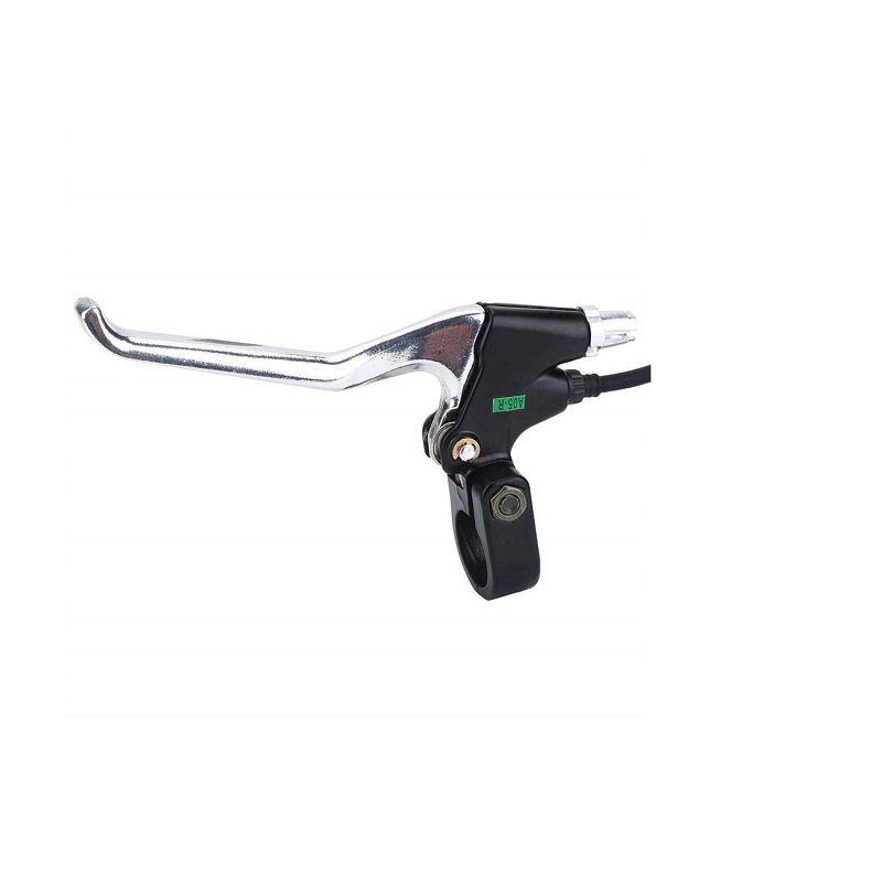
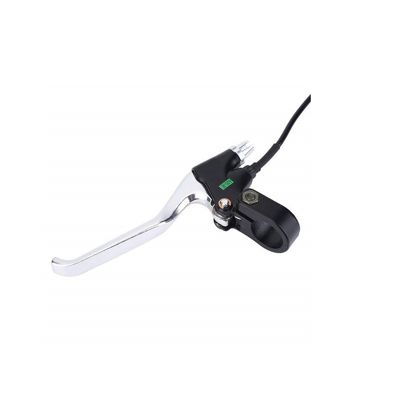
The Electric Bike Brake Lever with Motor Cut-Off Switch is an electrical brake-control component for compatible electric bicycles and scooters. It combines a handlebar-mounted lever with an integrated electrical switch that signals the motor controller when the brake is applied.
When connected to a compatible controller’s low-level brake input, operating the lever can interrupt motor drive during braking. This helps prevent the motor from continuing to provide propulsion while the rider is applying the brake.
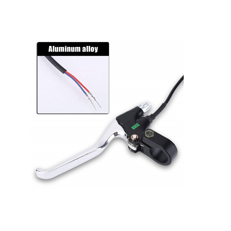
The assembly uses aluminium and plastic construction and is designed for handlebars with a 22.5mm mounting diameter. An approximately 1.5m low-level brake cable provides the electrical connection to the controller. The switch wiring is non-polarised, so either wire can be connected to the corresponding brake-switch circuit terminals.
Technical Features & Functional Characteristics
- Integrated Electrical Brake Switch: Provides a switching signal when the brake lever is operated, allowing a compatible controller to interrupt motor drive.
- Low-Level Brake Signal: Designed for controllers with a compatible low-level electrical brake input.
- Non-Polarised Cable Connection: The brake-switch cable has no positive or negative polarity distinction, simplifying connection to compatible switch terminals.
- Aluminium & Plastic Body: Combines aluminium and plastic components in the handlebar brake lever assembly.
- 22.5mm Handlebar Fitment: Intended for handlebars with the specified mounting diameter.
- Extended Cable Length: The approximately 1.5m cable supports routing from the handlebar to the controller connection point.
- V-Brake Lever Style: Uses a bicycle-style lever arrangement for compatible handlebar installations.
- Replacement Component: Suitable for replacing a damaged or worn electric brake lever where the mounting and electrical interfaces match.
Motor Cut-Off Function & Electrical Operation
The integrated electrical switch is intended to work with a motor controller that supports a compatible low-level brake input. When the lever is operated, the switch changes its electrical state and sends a brake signal to the controller. The controller can then interrupt motor drive according to its brake-input logic.
This function provides an additional electrical control alongside the mechanical braking system. It does not replace the physical brake mechanism and should not be treated as the vehicle’s primary braking system.
The brake cable is non-polarised, meaning its two switch wires do not have fixed positive and negative connections. However, the controller’s brake-input terminals and signal requirements must still be matched correctly before connection.
Handlebar Mounting & Cable Connection
The lever is designed for handlebars with a 22.5mm mounting diameter. It should be positioned so that the rider can operate it comfortably without interference from the throttle, display, grips or other handlebar controls.
The approximately 1.5m cable is routed from the lever to the compatible motor controller. Keep the cable clear of moving steering parts, sharp edges and hot components, and provide sufficient slack for full handlebar movement.
- Handlebar Fitment: Use on a compatible 22.5mm mounting section.
- Controller Connection: Connect the two switch wires to the controller’s compatible low-level brake input.
- Wire Polarity: Either switch wire can be connected to either corresponding brake-switch terminal; the switch itself has no positive or negative polarity distinction.
- Cable Routing: Secure the cable neatly while allowing free steering movement and avoiding excessive bending or pulling.
Applications
- Electric Bicycles: For compatible e-bike handlebar assemblies requiring an electrical motor cut-off signal during braking.
- Electric Mountain Bikes: For compatible electric mountain-bike brake-control systems using a 22.5mm handlebar mounting section.
- Electric Road Bikes: For e-road bicycle configurations with matching lever mounting and controller brake-input requirements.
- Electric Scooters: For compatible scooter handlebar systems using an electrical low-level brake switch.
- E-Bike Conversion Kits: For conversion projects using a motor controller with a compatible low-level brake input.
- Electric Vehicle Maintenance: For replacing a worn or damaged brake lever assembly with a matching mechanical and electrical interface.
- DIY Electric Bicycle Projects: For custom electric bicycle builds requiring handlebar-operated motor cut-off control.
Package Contents
| Quantity | Component |
|---|---|
| 1 | Electric Bike Brake Lever with Integrated Motor Cut-Off Switch and Cable |
Product Specifications
| Parameter | Specification |
|---|---|
| Product Category | Electric Bicycle Brake Control |
| Item Type | Electric Bike Brake Lever |
| Handle Type | Lever |
| Lever Style | V-Brake style |
| Construction Material | Aluminium + Plastic |
| Handlebar Mounting Diameter | 22.5mm |
| Electrical Function | Motor cut-off brake switch |
| Brake Signal Type | Low-level brake signal |
| Cable Wire Length | Approximately 1.5m (59.05 inches) |
| Wire Polarity | Non-polarised; no positive or negative wire distinction |
| Colour | Black and Silver |
| Compatible Vehicle Types | Compatible electric bicycles and scooters |
| Package Quantity | 1 brake lever assembly |
Installation & Operating Recommendations
Install the lever on a compatible handlebar section and connect its switch cable to the motor controller’s low-level brake input. Correct mechanical positioning and electrical compatibility are important for the brake cut-off function to operate as intended.
- Confirm Handlebar Diameter: Ensure the mounting section is compatible with the specified 22.5mm fitment.
- Check Controller Brake Input: Use with a controller that supports a compatible low-level brake switch signal.
- Connect the Switch Wires: Connect the two non-polarised wires to the corresponding brake-switch input terminals according to the controller wiring diagram.
- Position the Lever Correctly: Set the lever angle and reach for comfortable operation without interference from other handlebar controls.
- Route the Cable Safely: Keep the 1.5m cable away from sharp edges, hot surfaces and moving components. Allow enough slack for full steering movement.
- Test the Motor Cut-Off: With the drive wheel safely raised, verify that operating the brake lever activates the controller’s motor cut-off function.
- Check Mechanical Braking: Ensure the vehicle’s physical braking system is correctly adjusted and functions independently of the electrical cut-off switch.
- Inspect Cable Condition: Check the cable and connections periodically for damage, looseness or exposed conductors.