
SPIDER Automation | Cligo 4WD Arduino Smart Robot Car Kit | Integrated Mobile Robotics & Sensor Control Platform
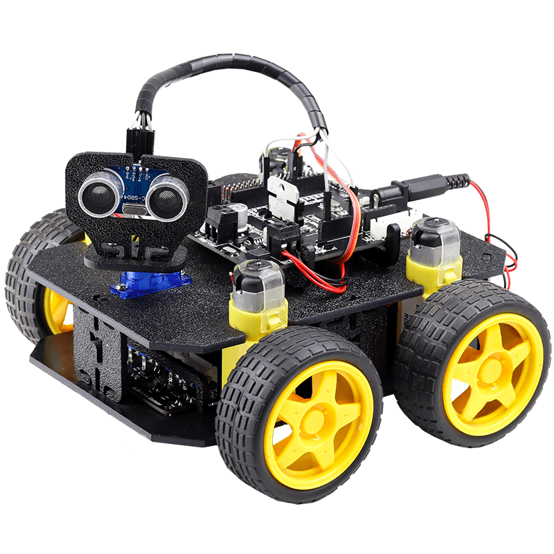
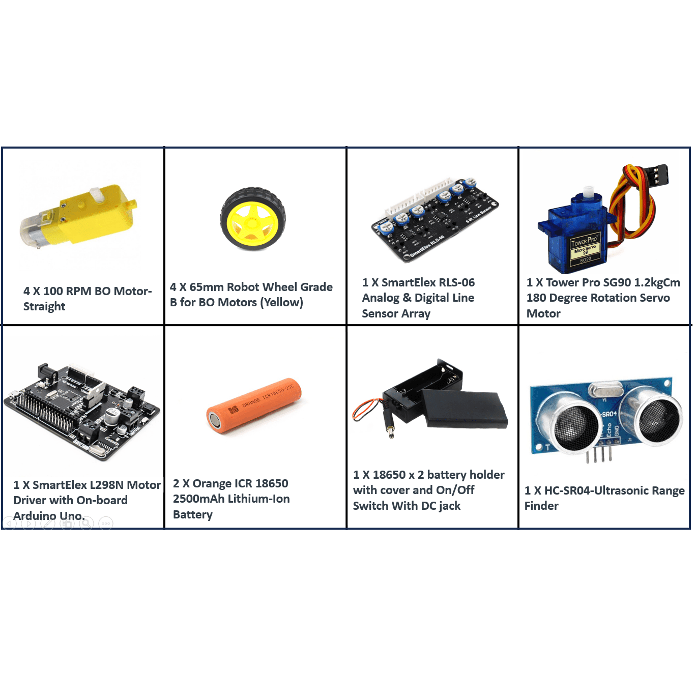
The SPIDER Automation Cligo 4WD Arduino Smart Robot Car Kit is an integrated mobile robotics development platform combining a four-wheel-drive mechanical assembly with an Arduino UNO controller, L298N motor driver, line sensor array, ultrasonic distance sensor, servo motor and infrared remote-control module. The system brings together the principal hardware required to develop programmable robot movement and sensor-based responses. Four 100 RPM BO geared motors drive the supplied 65mm wheels, while the integrated control electronics provide the foundation for implementing motor commands and interfacing with the included sensing modules.
The mechanical platform uses a modular ABS snap-fit chassis designed to accommodate the drive motors, control electronics, power components and sensor accessories. Its sensor configuration includes an analog and digital line sensor array and an HC-SR04 ultrasonic range finder, while the SG90 servo provides 180-degree positioning for suitable mounted mechanisms. The package also includes two 2500mAh 18650 lithium-ion cells, a two-cell battery holder with an On/Off switch and DC jack, a dual-slot battery charger, jumper-wire sets and assembly accessories. This combination supports the development of embedded control, mobile movement, line sensing, distance measurement and remote-command functions in one configurable robot platform.
Product Overview & Modular Chassis Design
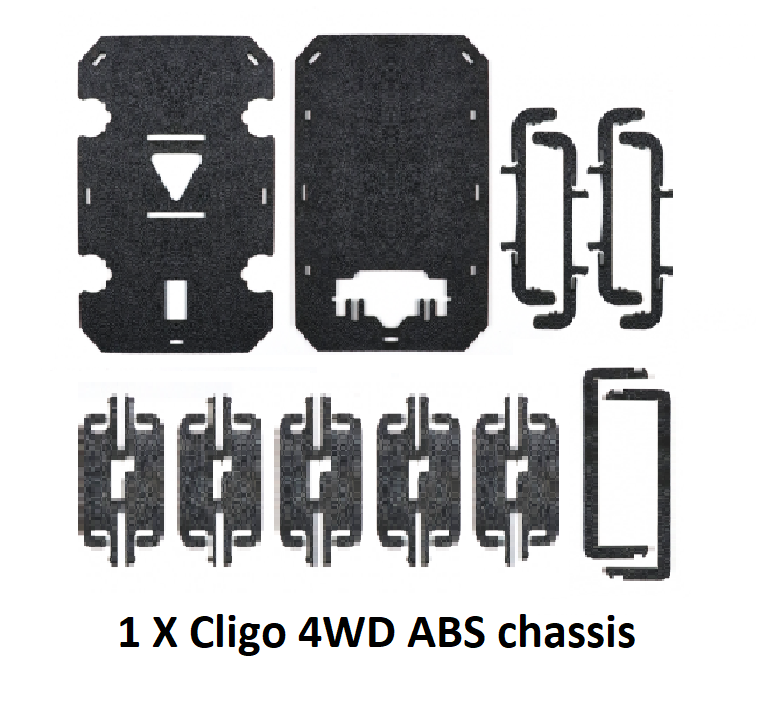
The Cligo platform uses a modular ABS plastic chassis with snap-fit panels and mounting provisions for its drive system and electronic components. The snap-fit construction is intended to simplify mechanical assembly without requiring conventional tools for joining the chassis panels. The supplied screwdriver is intended for mounting the servo motor and related assembly work.
The chassis provides a common mounting structure for the four drive motors, controller and motor-driver assembly, battery holder and sensor accessories. The supplied ultrasonic sensor bracket is also designed around the chassis’s snap-fit mounting approach. This modular arrangement makes it possible to configure the platform around different combinations of movement, sensing and control functions.
- ABS Chassis Construction: Plastic structural panels provide the mechanical framework for the mobile robot.
- Snap-Fit Assembly: Interlocking chassis components simplify assembly and reduce the need for separate panel-fastening tools.
- Component Mounting: The platform accommodates the supplied drive, control, sensing and power components.
- Sensor Bracket: A dedicated snap-fit bracket is included for mounting the HC-SR04 ultrasonic sensor.
Four-Wheel-Drive System & Motor Configuration
The robot uses a four-wheel-drive arrangement with four straight BO geared motors and four 65mm wheels. Each motor provides a geared output for driving its corresponding wheel. The stated motor speed is 100 RPM, providing the nominal speed reference for the supplied motor configuration.
The L298N motor-driver assembly interfaces the controller with the DC motors. Appropriate motor-control programming can be used to implement movement commands and directional changes. Actual movement behaviour depends on the motor wiring, driver configuration, power supply, wheel contact and programmed control logic.
- Four BO Geared Motors: Four straight DC geared motors provide the powered drive arrangement.
- 100 RPM Motor Speed: The stated motor speed provides a reference for configuring the drive system.
- 65mm Wheels: Four yellow robot wheels connect to the motor drive assemblies.
- Motor Driver Interface: The L298N board provides the motor-driving stage between the Arduino controller and the DC motors.
- Programmable Movement: Controller programming can implement forward, reverse, turning and other movement sequences supported by the motor wiring and driver configuration.
Arduino UNO Controller & L298N Motor Driver
The supplied electronics assembly combines an Arduino UNO controller with an L298N motor driver. This integrated arrangement provides the processing and motor-control foundation for the robot platform. The controller can execute programmed instructions, read compatible sensor signals and issue movement commands through the motor-driver circuitry.
The Arduino-compatible control environment allows the platform to be configured for different combinations of motor movement, line sensing, ultrasonic distance measurement, servo positioning and infrared remote input. The included Micro USB cable provides the physical connection for compatible programming and controller communication.
The L298N motor driver has electrical and thermal operating limits. Because the platform uses four motors, the combined motor load and driver configuration must be verified before connecting the complete drive system. The exact motor-channel wiring and current capacity for continuous four-motor operation should be checked before full-load use.
Line Detection & Tracking Sensor Array
The included analog and digital line sensor array provides line-detection inputs for programmable mobile robotics applications. The sensor array can be interfaced with the Arduino controller to detect changes in the surface beneath the sensor elements. The controller can then use the detected signal pattern to generate suitable motor-control commands.
This sensing arrangement provides the hardware foundation for line-following and line-tracking implementations. Actual tracking behaviour depends on sensor positioning, surface contrast, sensor calibration, signal interpretation and the control algorithm used in the Arduino program.
Ultrasonic Distance Measurement & Servo Positioning
The kit includes an HC-SR04 ultrasonic range finder for distance-measurement applications. The sensor uses ultrasonic transmission and reception to estimate the distance to a reflecting object. Its readings can be processed by the Arduino controller to implement proximity-responsive movement and obstacle-detection logic.
A matching snap-fit ABS bracket is included to mount the ultrasonic sensor to the chassis. The kit also contains an SG90 servo motor with a stated 180-degree rotation range and 1.2 kg·cm torque rating. The servo can position a compatible mounted component, including a sensor assembly, where the mechanical mounting arrangement and load are suitable.
- Ultrasonic Sensing: HC-SR04 module for distance measurement and proximity-related control functions.
- Sensor Mounting: Dedicated ABS snap-fit bracket for the ultrasonic sensor.
- Servo Positioning: SG90 servo provides a stated 180-degree rotation range.
- Servo Torque: Stated torque rating of 1.2 kg·cm.
- Controller Integration: Sensor readings and servo commands can be incorporated into Arduino-based control programs.
Infrared Remote-Control Interface
The included infrared wireless remote-control module provides a manual command-input option. The receiver interfaces with the controller, allowing compatible remote commands to be interpreted by the programmed system. This enables the robot to be configured for remote-operated movement and other control functions supported by the software.
The IR module can be used independently of sensor-based movement logic or incorporated into a program that combines manual commands with sensor inputs. Remote-control functionality depends on the receiver connection, remote protocol and corresponding decoding implementation.
Battery Power System & Charging Accessories
The package includes two 18650 lithium-ion cells rated at 2500mAh each, along with a two-cell battery holder featuring a protective cover, On/Off switch and DC jack. This provides the supplied battery hardware for powering the assembled robot according to the intended electrical configuration.
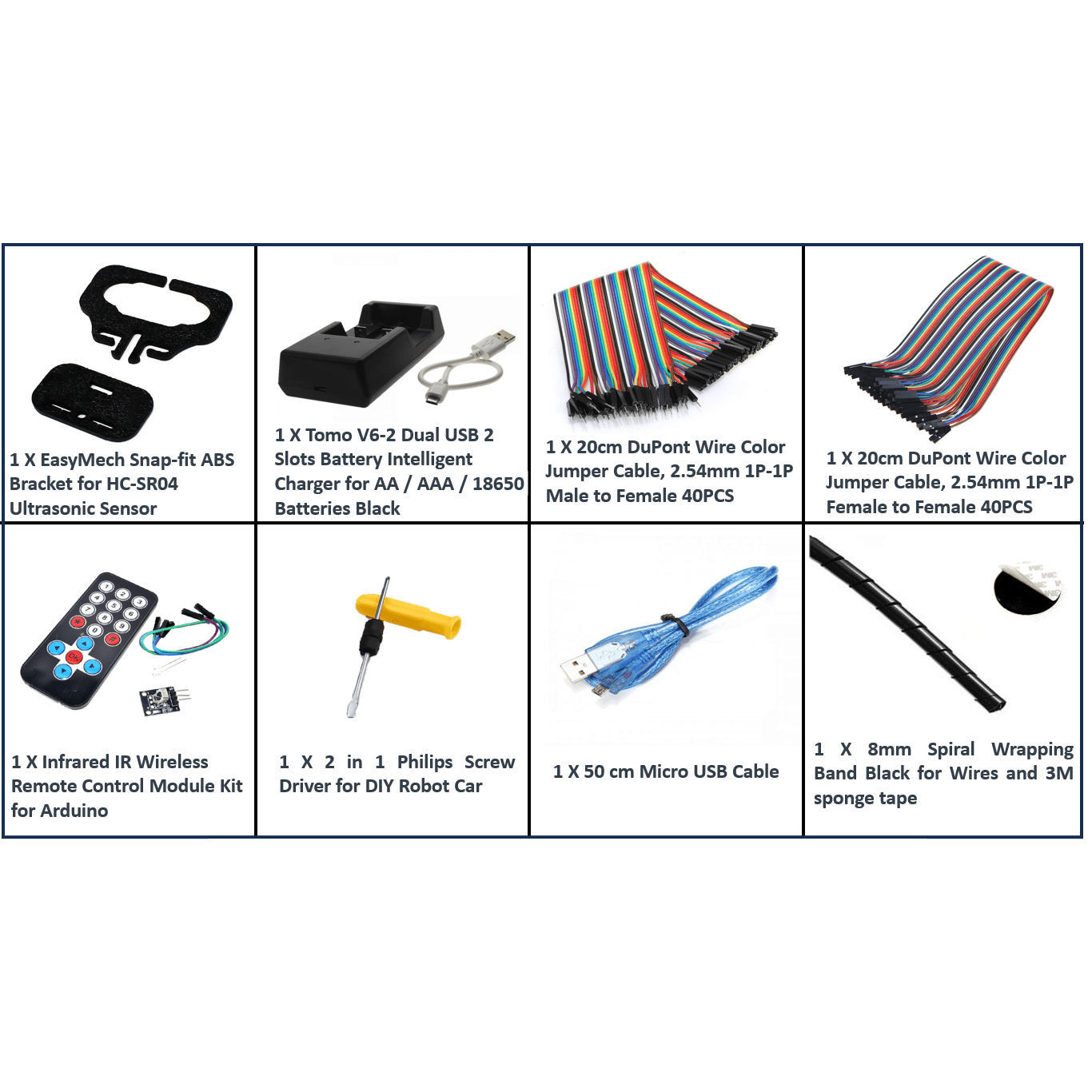
A two-slot USB battery charger is also included. It is described as supporting AA, AAA and 18650 battery formats. Battery charging must be carried out using the appropriate charger configuration and compatible cells. The exact battery-holder wiring topology and the complete robot’s required supply voltage are not established, so the electrical configuration should be verified before connecting the battery pack to the controller and motor driver.
Applications
The combination of four-wheel drive, programmable control, line sensing, ultrasonic measurement, servo positioning and infrared remote input makes this kit suitable for developing and demonstrating a range of mobile robotics functions.
- Arduino Mobile Robot Development: Building programmable four-wheel-drive robots using an Arduino UNO controller and DC motor-driver interface.
- Four-Wheel-Drive Motion Control: Developing motor-control logic for a four-motor mobile platform.
- Line-Following Systems: Implementing line detection and tracking using the included analog and digital sensor array.
- Ultrasonic Obstacle Detection: Developing distance-based responses using the HC-SR04 ultrasonic range finder.
- Remote-Controlled Robot Systems: Implementing manual movement commands through the included infrared remote-control module.
- Servo-Based Sensor Positioning: Using the SG90 servo to position compatible sensor or accessory assemblies.
- Sensor-Fusion Prototypes: Combining line-sensor readings, ultrasonic measurements and remote commands within one controller program.
- Embedded Programming Development: Testing Arduino-based input processing, motor control, timing and conditional logic.
- Mobile Robotics Integration: Developing a compact system that combines mechanical drive, sensing, power and embedded electronics.
- Robotics Technical Demonstrations: Demonstrating four-motor drive, line detection, ultrasonic sensing and wireless command input.
Package Includes
- 1 × Cligo 4WD ABS Chassis.
- 4 × 100 RPM Straight BO Geared Motors.
- 4 × 65mm Yellow Robot Wheels – Grade B for BO motors.
- 1 × Analog and Digital Line Sensor Array – RLS-06.
- 1 × SG90 Servo Motor – 1.2 kg·cm, 180-degree rotation.
- 1 × L298N Motor Driver Assembly with Onboard Arduino UNO Controller.
- 2 × 18650 Lithium-Ion Batteries – 2500mAh each.
- 1 × Two-Cell 18650 Battery Holder – with cover, On/Off switch and DC jack.
- 1 × HC-SR04 Ultrasonic Range Finder.
- 1 × Snap-Fit ABS Ultrasonic Sensor Bracket.
- 1 × Dual-Slot USB Battery Charger – for AA, AAA and 18650 battery formats.
- 1 × 20cm Male-to-Female Dupont Jumper Wire Set – 40 pieces, 2.54mm, 1P-1P.
- 1 × 20cm Female-to-Female Dupont Jumper Wire Set – 40 pieces, 2.54mm, 1P-1P.
- 1 × Infrared Wireless Remote-Control Module Kit.
- 1 × 2-in-1 Phillips Screwdriver.
- 1 × 50cm Micro USB Cable.
- 1 × 8mm Black Spiral Cable-Wrapping Band.
- 1 × 3M Multipurpose Double-Sided Sponge Adhesive Pad.
- 1 × Assembly and Operating Manual.
Product Specifications
| Parameter | Specification |
|---|---|
| Product Type | Arduino smart robot car kit |
| Platform Configuration | Four-wheel-drive mobile robot platform |
| Chassis Type | Modular snap-fit chassis |
| Chassis Material | ABS plastic |
| Platform Width | 145mm |
| Platform Height | 80mm |
| Platform Length | Not established |
| Drive Motor Quantity | 4 |
| Drive Motor Type | Straight BO DC geared motors |
| Motor Speed | 100 RPM (stated motor speed) |
| Motor Operating Voltage | Not established |
| Motor Current | Not established |
| Wheel Quantity | 4 |
| Wheel Diameter | 65mm |
| Wheel Type | Grade B robot wheels for BO motors |
| Wheel Colour | Yellow |
| Controller | Arduino UNO onboard the supplied motor-driver assembly |
| Motor Driver | L298N dual H-bridge motor driver assembly |
| Line Sensor Module | RLS-06 analog and digital line sensor array |
| Ultrasonic Sensor | HC-SR04 ultrasonic range finder |
| Ultrasonic Sensor Mount | Snap-fit ABS bracket |
| Servo Motor | SG90 micro servo |
| Servo Torque | 1.2 kg·cm (stated rating) |
| Servo Rotation | 180 degrees (stated range) |
| Remote-Control Interface | Infrared wireless remote-control module |
| Battery Type | 18650 lithium-ion cells |
| Battery Quantity | 2 cells |
| Battery Capacity | 2500mAh per cell (stated capacity) |
| Battery Holder | Two-cell 18650 holder with cover, On/Off switch and DC jack |
| Battery Charger | Dual-slot USB charger for AA, AAA and 18650 battery formats |
| Jumper Wire Set 1 | 40 × male-to-female Dupont wires, 20cm, 2.54mm, 1P-1P |
| Jumper Wire Set 2 | 40 × female-to-female Dupont wires, 20cm, 2.54mm, 1P-1P |
| USB Cable | 50cm Micro USB cable |
| Assembly Tool | 2-in-1 Phillips screwdriver |
| Cable Management Accessory | 8mm black spiral wrapping band |
| Adhesive Accessory | 3M multipurpose double-sided sponge adhesive pad |
| Documentation | 1 assembly and operating manual |
| Product Weight | 975g (stated product weight) |
| Recommended Age | 10 years and above (stated recommendation) |
Installation & Operating Recommendations
- Follow the Assembly Sequence: Assemble the ABS snap-fit chassis according to the supplied manual. Avoid squeezing or twisting the small snap-fit tabs with pliers, as excessive force can break the chassis features.
- Use the Supplied Screwdriver: The screwdriver is included for mounting the servo and completing the required mechanical fastening operations.
- Verify Motor Wiring: Check the motor connections and channel assignments before applying power. Confirm the direction of each wheel using controlled, short-duration tests.
- Check L298N Current Capacity: Verify the driver board’s actual current and thermal limits against the combined operating and starting requirements of all four motors. Do not assume that the board can continuously drive four motors at their maximum load merely because the kit includes four motors.
- Confirm Battery Configuration: Check the two-cell holder’s wiring topology, output voltage and polarity before connecting it to the controller and motor driver. Do not assume a series or parallel connection without verification.
- Check Cell Compatibility: Confirm that both supplied 18650 cells are compatible with the holder and charging equipment. Use the included charger only according to its instructions and the cell manufacturer’s charging requirements.
- Separate Power Requirements: Verify the supply requirements of the motors, controller, sensors and servo. Use an appropriate regulated supply where required, and ensure the motor-driver and controller connections share the required electrical reference.
- Position the Line Sensor Array: Mount the sensor array at a suitable height and alignment relative to the operating surface. Calibrate the sensor readings for the actual line and background contrast before implementing tracking logic.
- Mount the Ultrasonic Sensor Securely: Fit the HC-SR04 to its supplied bracket and check that the sensor faces the intended measurement direction without obstruction.
- Check Servo Loading: Keep the mounted load within the servo’s practical operating capability. Avoid forcing the servo beyond its mechanical travel limits.
- Route Wiring Carefully: Use the supplied jumper wires and spiral wrapping band to organise connections. Keep wires clear of the wheels, motor shafts and moving servo components.
- Test Functions Individually: Verify motor movement, line sensing, ultrasonic readings, servo positioning and infrared remote input separately before combining them in a complete control program.
- Monitor Operating Temperature: During initial tests, monitor the motor driver, motors and power connections for excessive heating. Stop operation if components become unusually hot or connections loosen.