
SPIDER Automation | 85dB Lost Aircraft Alarm Finder & Signal Loss Tracer Buzzer | Inline 4V-6V Receiver Protection
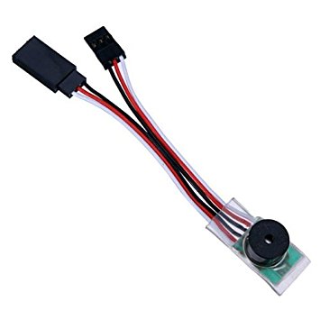
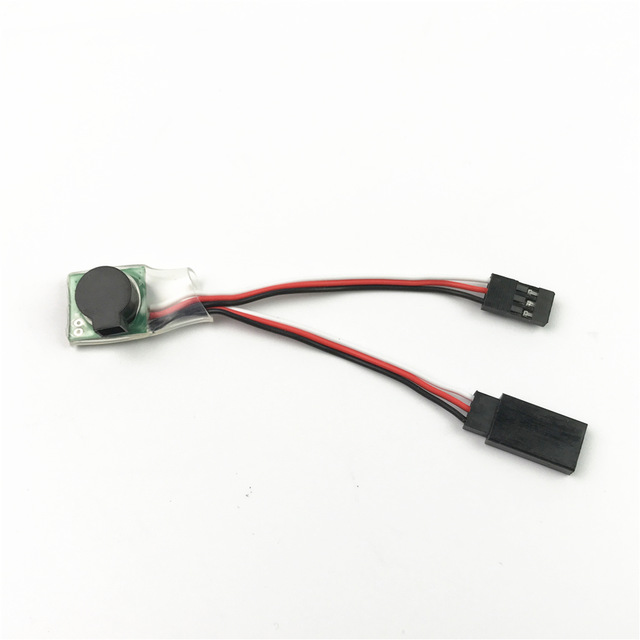
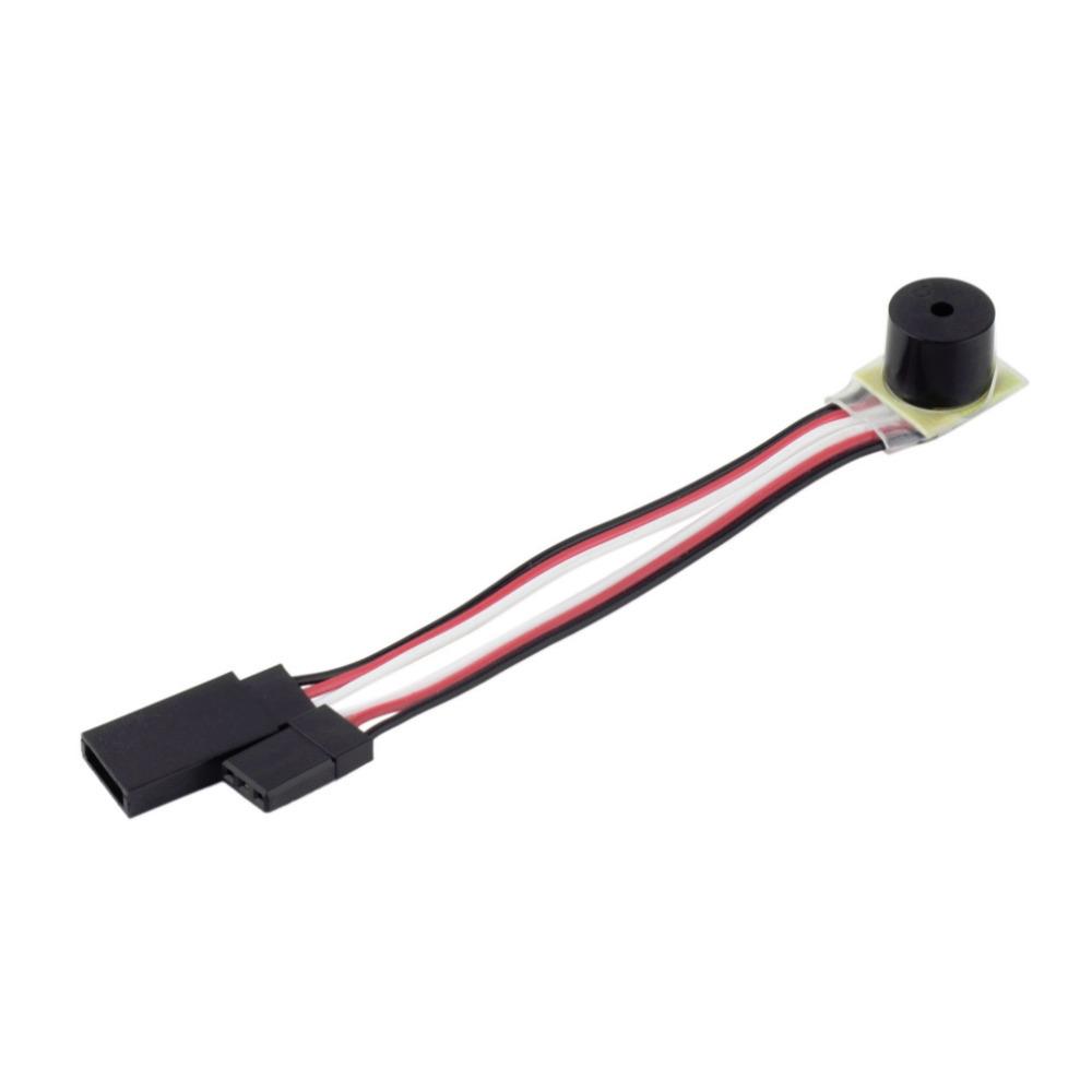
The SPIDER Automation 85dB Lost Aircraft Alarm Finder & Signal Loss Tracer Buzzer (Model: RC-LOST-ALARM-85DB) is a specialized electronic telemetry and recovery diagnostic tool designed for remote-controlled aerial platforms, autonomous mobile robots, and field testing rigs. Unexpected control link disengagements, power shutdowns, or crashes into tall vegetation often result in lost hardware and expensive downtime. This inline signal-loss buzzer provides a reliable, self-actuating acoustic beacon that pinpoints the exact location of disengaged equipment.
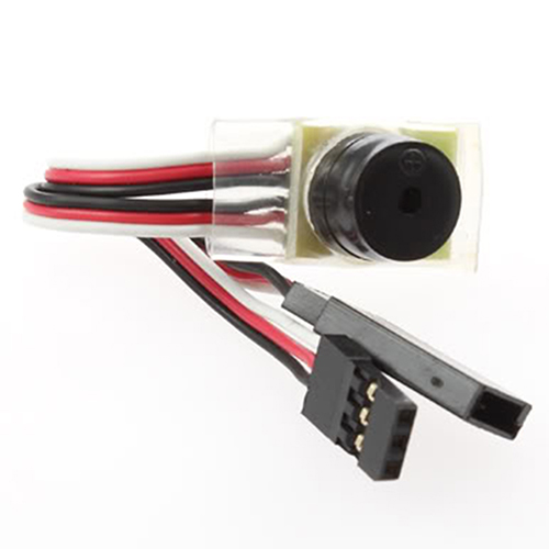
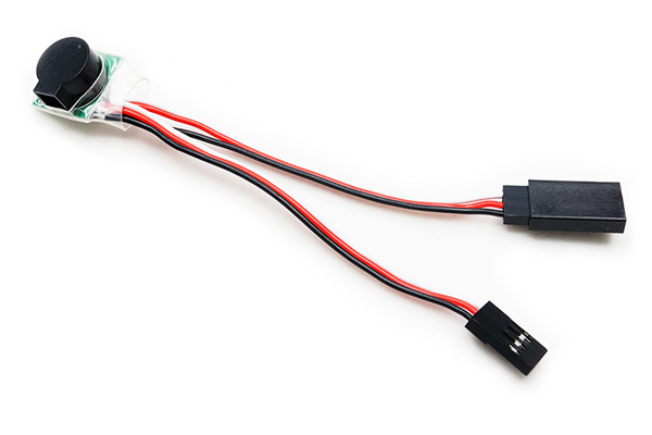
Engineered for effortless plug-and-play installation, the module operates inline between any standard receiver channel port and a servo actuator, functioning as an integrated pass-through extension cable. The internal control logic continuously samples incoming pulse-width control signals from the transmitter. If the radio signal is interrupted, or if control inputs remain static past a set duration, the module initiates a staged acoustic alert—starting with a distinct warning sequence and escalating to a high-volume 85dB continuous locating sound. Its low current consumption ensures prolonged acoustic emission without rapidly draining the main receiver power supply.
Product Overview & Functional Design
The RC-LOST-ALARM-85DB tracer module offers a practical, low-cost safety net for unmanned vehicles operating in high-risk outdoor environments or expansive field-testing grounds. By integrating directly into existing PWM servo wiring harnesses, it requires no external microcontrollers, secondary battery supplies, or complex software programming.
Upon initial receiver power-up with an active transmitter link, the module sounds two confirmation beeps to indicate operational readiness. During active operation, command signals pass through to the connected servo without latency or signal attenuation. If signal communication drops or the transmitter is powered down, the internal timing circuit executes a two-stage alert sequence, shifting to maximum acoustic output to guide operators directly to the asset.
Technical Features & Functional Characteristics
- High-Volume 85dB Sound Output: Integrated piezo buzzer generates a piercing acoustic signal legible over long outdoor distances.
- Automatic Radio Signal Monitoring: Constantly evaluates pulse integrity from the receiver to detect signal dropouts instantly.
- Multi-Stage Alarm Escalation: Progresses from a preliminary continuous warning beep to a higher-pitch, maximum-volume locator tone.
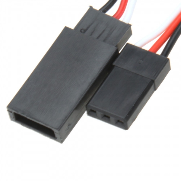
- Direct Inline Pass-Through Architecture: Acts as a male-to-female servo extension harness, eliminating extra splitters or power taps.
- Universal Receiver Bus Voltage: Operates reliably across standard 4V to 6V DC auxiliary supply lines.
- Ultra-Low Current Consumption: Draws between 1 mA (idle) and 35 mA (active alarm state), minimizing system power draw.
- Flexible Wire Harness Construction: Flexible 140mm total length allows easy routing around tight chassis cutouts and structural frames.
- Polarity-Keyed Connection Interface: Standard 3-pin connector layout ensures straightforward attachment to receiver outputs.
- Rugged Surface-Mount Electronics: Built with solid-state components designed to endure high-vibration and high-g operational environments.
Signal Loss Detection Logic & Operational Sequence
The tracer module features a smart monitoring sequence designed to differentiate between active control inputs and signal failure states.
- System Initialization: Powering up the receiver with an active transmitter connection produces 2 short confirmation beeps.
- Signal Loss Activation: If the transmitter signal is lost or left un-actuated for 5 minutes, the module initiates a continuous beep alert.
- Acoustic Level Escalation: If the initial alert remains unacknowledged for approximately 2 minutes, the buzzer escalates to a louder, higher-frequency V-sound pattern for maximum audibility.
- Alarm Reset Mechanism: Re-establishing transmitter signal link or actuating a control stick automatically resets the alarm timing circuit.
Applications
The RC-LOST-ALARM-85DB tracer buzzer is ideal for mobile platform installations where visual tracking is lost or recovery in dense terrain is required.
- Unmanned Aerial Vehicles (UAVs): Acoustic locator beacon for fixed-wing aircraft, multi-rotors, and parkflyer gliders lost in long grass or trees.
- Autonomous Mobile Robots (AMRs): Emergency signal-loss alarm for field inspection rovers and long-range ground vehicles.
- RC Gliders & Sailplanes: Essential recovery tracer for high-altitude thermal gliders operating near visual limits.
- Pit Power Warning System: Serves as an audible alert if receiver power is accidentally left switched on while the transmitter is off in pit areas.
- Industrial Test Equipment: Diagnostic signal-loss indicator for remote control research setups and experimental drive platforms.
Package Includes
- 1 × SPIDER Automation 85dB Lost Aircraft Alarm Finder & Signal Loss Tracer Buzzer (Model: RC-LOST-ALARM-85DB)
Product Specifications
| Parameter | Specification |
|---|---|
| Brand / Distributor | SPIDER Automation |
| Model Number | RC-LOST-ALARM-85DB |
| Product Type | Lost Aircraft Alarm Finder / Signal Loss Tracer Buzzer |
| Sound Level Output | 85 dB |
| Operating Voltage Rating | 4.0V DC to 6.0V DC |
| Continuous Drain Current | 1 mA to 35 mA |
| Module Length | 140 mm (Total Harness Length) |
| Module Width | 9 mm |
| Module Height | 10 mm |
| Product Net Weight | 4.5 g |
| Module PCB Colour | Green |
| Interface Connection Type | Standard 3-Pin Servo Pass-Through Connector |
| Detection Method | PWM Servo / RX Pulse Signal Loss Monitoring |
| Shipping Package Weight | 0.050 kg (50 grams) |
| Shipping Dimensions (L × W × H) | 4 cm × 3 cm × 2 cm |
Installation & Operating Guidelines
Standard wiring and polarity orientation practices should be strictly observed during mechanical integration into control systems.
- Inline Connection: Connect the male plug of the alarm module into the desired receiver channel output port, then connect the servo lead into the female socket of the alarm module.
- Polarity Alignment: Observe correct pin polarity (Signal, Positive, Ground) prior to energizing the receiver bus.
- Power Supply Requirements: Ensure the receiver power bus operates strictly within the rated 4.0V to 6.0V DC range.
- Deactivation: Disconnecting the module from the receiver power bus completely switches off the internal acoustic circuit.