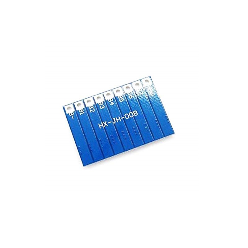

SPIDER Automation | 8S 29.6V Lithium-Ion Battery Balancer Board | 4.2V Cell Balancing
Product Overview
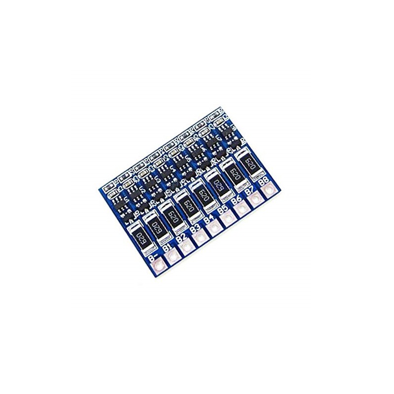
The SPIDER Automation 8S Lithium-Ion Battery Balancer Board is designed for cell-voltage balancing in battery packs consisting of eight lithium-ion cells connected in series. It uses a shunt-balancing approach, in which a higher-voltage cell is discharged through a balancing path to help reduce voltage differences between individual cells during charging.
For a conventional lithium-ion configuration using 3.7V nominal cells, an 8S battery pack has a 29.6V nominal voltage and a 33.6V full-charge voltage, based on 4.2V per cell. The board specifies a 4.2V per-cell balancing voltage and a 66mA discharge shunt balancing current. Its compact PCB measures 37.3 × 25.8 × 2.4mm.
Technical Features & Construction
- 8S Battery Configuration: Intended for eight series-connected lithium-ion cells.
- Shunt Balancing Architecture: Uses a discharge balancing path to reduce voltage differences between higher-voltage cells and the remaining cells.
- 4.2V Cell Balancing Voltage: Specified balancing voltage for conventional 4.2V maximum-charge lithium-ion cells.
- 66mA Balancing Current: Specified discharge shunt balancing current of 66mA.
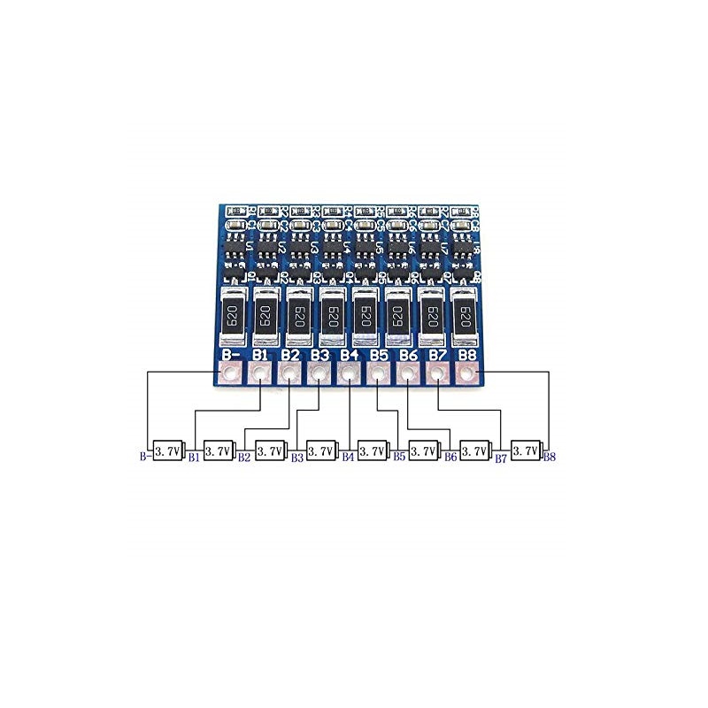
- Individual Cell Connections: Uses labelled solder points for battery negative and successive cell junctions.
- Compact PCB Design: Board dimensions of 37.3 × 25.8 × 2.4mm for integration into suitable battery assemblies.
- Auxiliary Balancing Function: Intended to support cell-voltage equalization and does not replace a dedicated battery protection system.
Electrical Configuration & Battery Voltage
The board is intended for an 8S lithium-ion battery configuration. In a series-connected arrangement, the individual cell voltages add together to determine the overall battery pack voltage.
| Electrical Parameter | Value |
|---|---|
| Battery Configuration | 8S – Eight cells connected in series |
| Nominal Cell Voltage | 3.7V per cell |
| Nominal Pack Voltage | 29.6V |
| Full-Charge Cell Voltage | 4.2V per cell |
| Full-Charge Pack Voltage | 33.6V |
| Balancing Method | Discharge shunt balancing |
| Balancing Voltage | 4.2V per cell |
| Balancing Current | 66mA |
Cell Balancing Operation
During charging, individual cells in a series-connected battery pack may reach different voltage levels because of variations in cell characteristics and operating conditions. A shunt balancer provides a controlled discharge path for a cell that reaches its balancing threshold, allowing the other cells to continue approaching their corresponding voltage levels.
This board specifies a 66mA discharge shunt balancing current at a 4.2V per-cell balancing level. It is an auxiliary cell-balancing component. The battery pack must use a suitably configured BMS for its required charging and discharging protection functions.
Solder Terminal & Connection Details
The described terminal sequence includes solder points labelled B through B7, corresponding to the battery negative connection and successive cell junctions. The complete 8S connection arrangement requires a positive-end connection after the eighth cell; its terminal designation is not provided in the available connection details.
| Terminal | Described Connection |
|---|---|
| B | Negative terminal of the battery pack. |
| B1 | Junction between Cell 1 and Cell 2. |
| B2 | Junction between Cell 2 and Cell 3. |
| B3 | Junction between Cell 3 and Cell 4. |
| B4 | Junction between Cell 4 and Cell 5. |
| B5 | Junction between Cell 5 and Cell 6. |
| B6 | Junction between Cell 6 and Cell 7. |
| B7 | Junction between Cell 7 and Cell 8. |
Applications
The 8S balancer board is intended for compatible eight-series lithium-ion battery assemblies where an auxiliary cell-voltage balancing function is required.
- 8S 18650 Battery Packs: Cell-balancing applications in eight-series 18650 lithium-ion battery assemblies.
- 8S Lithium-Ion Battery Modules: Integration into compatible modular battery configurations.
- Electric Mobility Battery Systems: Potential use in suitable 8S battery configurations for electric mobility projects.
- Portable Power Storage Units: For compatible rechargeable battery assemblies used in portable DC power systems.
- DC Backup Power Systems: Auxiliary balancing in suitable 8S lithium-ion backup battery configurations.
- Rechargeable Energy Storage Projects: Cell-voltage balancing in compatible battery-based energy storage designs.
- Custom Battery Pack Development: For development of eight-series lithium-ion battery assemblies.
- Battery Pack Prototyping: Integration into 8S battery development and electronic engineering projects.
- Portable DC Equipment: Potential use in compatible battery-powered equipment designed around an 8S pack.
- DIY Lithium-Ion Battery Assemblies: For custom battery projects requiring an auxiliary 8S cell-balancing circuit.
Package Contents
- 8S Lithium-Ion Battery Balancer Board: 1 unit.
Product Specifications
| Parameter | Specification |
|---|---|
| Product Type | Lithium-Ion Battery Balancer Board |
| Battery Configuration | 8S – 8 cells in series |
| Battery Cell Format | 18650-compatible battery pack application |
| Battery Chemistry | Lithium-Ion |
| Nominal Cell Voltage | 3.7V |
| Nominal Pack Voltage | 29.6V |
| Full-Charge Pack Voltage | 33.6V |
| Balancing Method | Discharge shunt balancing |
| Balancing Voltage | 4.2V per cell |
| Balancing Current | 66mA |
| PCB Length | 37.3mm |
| PCB Width | 25.8mm |
| PCB Thickness | 2.4mm |
| Shipping Weight | 0.006kg |
| Shipping Dimensions | 6 × 5 × 1cm |
Connection & Operating Recommendations
- Correct Battery Configuration: Use only with a compatible 8S lithium-ion battery pack designed for 4.2V maximum-charge cells.
- Cell Junction Connections: Follow the verified PCB terminal diagram and connect each sensing point to its corresponding cell junction.
- Positive-End Terminal Confirmation: Confirm the eighth-cell positive terminal connection from the actual PCB marking or technical diagram before installation.
- Dedicated BMS Protection: Use a suitable 8S BMS for battery overcharge, over-discharge, overcurrent and short-circuit protection.
- Charging Compatibility: Use a charger specifically designed for an 8S conventional lithium-ion pack with a 33.6V full-charge voltage.
- Electrical Insulation: Ensure solder joints and exposed conductors are properly insulated to prevent accidental short circuits.