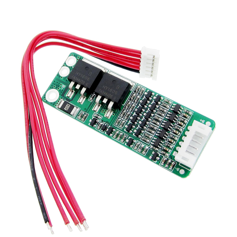

SPIDER Automation | 5S 15A 18650 Lithium-Ion Battery Management System | 21V Battery Protection Board with Connector Cable
Product Overview
The SPIDER Automation 5S 15A 18650 Lithium-Ion Battery Management System (BMS) is a battery protection board developed for rechargeable lithium-ion battery packs arranged in a five-series (5S) configuration. It monitors individual cell-group voltage conditions and provides protection against overcharging and excessive discharge, helping maintain battery operation within the intended voltage limits.
Designed for conventional 3.7V nominal lithium-ion cells, the board is intended for battery packs with an 18.5V nominal voltage and a 21V full-charge voltage. It supports a 15A continuous discharge current, making it suitable for compatible battery-powered equipment and custom battery assemblies requiring a 5S protection circuit.
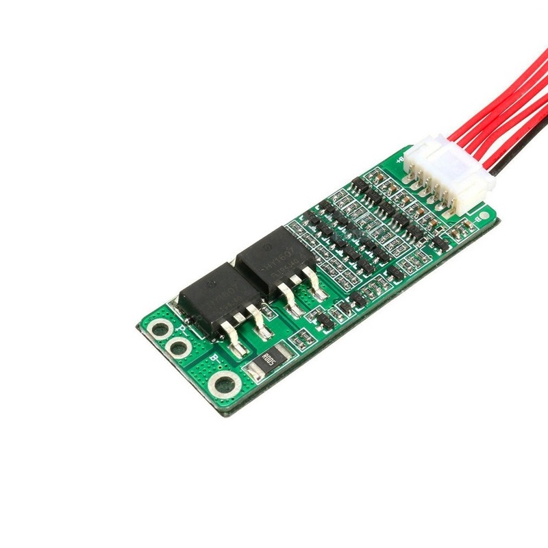
The protection circuit incorporates overcharge and over-discharge detection and recovery functions. Its compact PCB construction allows integration into compatible battery enclosures, while the included connector cable supports the battery-pack wiring arrangement.
Technical Features & Protection Functions
- 5S Cell Configuration: Designed for five lithium-ion cell groups connected in series to form an 18.5V nominal battery pack.
- Overcharge Detection: Monitors individual cell-group voltage during charging and provides protection against excessive cell voltage.
- Overcharge Recovery: The specified recovery range is 4.05–4.15V per cell group, allowing the protection circuit to recover when voltage returns to the recovery range.
- Over-Discharge Detection: Monitors cell-group voltage during discharge to help prevent excessive battery depletion.
- Over-Discharge Recovery: The specified recovery range is 2.90–3.20V per cell group.
- Voltage Monitoring: Monitors the voltage condition of the individual series-connected cell groups rather than relying only on total pack voltage.
- 15A Continuous Discharge Capability: Designed to support a continuous discharge current of up to 15A.
- Low-Power Monitoring Circuit: Incorporates low-current monitoring circuitry for battery protection operation.
- Connector Cable: Includes a connector cable to support the battery-pack connection arrangement.
Electrical Configuration & Battery Voltage
This protection board is designed for a 5S lithium-ion battery pack, where five cell groups are connected in series. For conventional lithium-ion cells with a nominal voltage of 3.7V and a full-charge voltage of 4.2V per cell group, the resulting pack voltage is:
| Cell Configuration | 5S (5 cell groups connected in series) |
| Nominal Cell Voltage | 3.7V |
| Nominal Pack Voltage | 18.5V |
| Full-Charge Cell Voltage | 4.2V |
| Full-Charge Pack Voltage | 21V |
The battery pack must use a compatible 5S lithium-ion configuration. The BMS is intended to operate with the corresponding cell-group connections and should not be used with a different series configuration.
Functional Advantages
- Individual Cell-Group Monitoring: Monitors cell-group voltage conditions within the series-connected battery pack.
- Charging Protection: Helps prevent individual cell groups from exceeding the intended charging voltage range.
- Discharge Protection: Helps prevent excessive discharge that can adversely affect lithium-ion cell performance and service life.
- Recovery Functions: Includes overcharge and over-discharge recovery voltage functions.
- 15A Discharge Rating: Supports battery-powered equipment with compatible continuous current requirements.
- Integrated PCB Assembly: Combines battery monitoring and protection circuitry on a compact circuit board.
Applications
The 5S 15A BMS can be integrated into compatible 18.5V nominal lithium-ion battery packs used in portable equipment, electronic systems and custom power assemblies.
- Electric Screwdrivers: Battery protection for compatible 5S rechargeable screwdriver battery packs.
- Cordless Power Tools: Suitable for compatible 18.5V nominal battery assemblies used in portable power tools.
- DIY 18650 Battery Packs: Protection circuitry for custom-built 5S lithium-ion battery packs.
- Robotics Projects: Battery management for compatible robotic platforms and mobile robots.
- Portable DC Equipment: Protection for rechargeable battery-powered devices designed around a 5S supply.
- Embedded Electronics: Battery protection in suitable embedded systems requiring a rechargeable lithium-ion power source.
- LED Lighting Systems: Battery management for compatible portable LED lighting assemblies.
- Electronic Prototyping: Integration into custom electronics projects using 5S lithium-ion battery packs.
- Portable Instruments: Protection for compatible battery-powered measuring and electronic instruments.
- Custom Rechargeable Power Systems: Battery protection for suitable 18.5V nominal power assemblies.
Package Contents
- 1 × 5S 15A 18650 Lithium-Ion Battery BMS Protection Board
- 1 × Connector Cable
Product Specifications
| Parameter | Specification |
|---|---|
| Product Type | Lithium-Ion Battery Management System (BMS) |
| Battery Chemistry | Lithium-Ion |
| Battery Configuration | 5S (5 series-connected cell groups) |
| Nominal Cell Voltage | 3.7V |
| Nominal Battery Voltage | 18.5V |
| Full-Charge Voltage | 21V |
| Continuous Discharge Current | 15A |
| Overcharge Recovery Voltage | 4.05–4.15V per cell group |
| Over-Discharge Detection Voltage | 2.75–2.85V per cell group |
| Over-Discharge Recovery Voltage | 2.90–3.20V per cell group |
| Protection Functions | Overcharge and over-discharge protection |
| Included Connection Accessory | Connector cable |
Connection & Operating Recommendations
- Correct Battery Configuration: Use this board only with a compatible 5S lithium-ion battery pack.
- Cell Compatibility: Assemble the pack using cells with compatible chemistry, capacity and condition.
- Charging Voltage: Use a dedicated 5S lithium-ion charger with a 21V output.
- Discharge Loading: Keep the continuous load current within the 15A discharge rating.
- Cell Connections: Connect the individual cell-group wiring according to the actual PCB markings and connection diagram.
- Connector Wiring: Follow the connector cable’s correct pin arrangement when integrating it into the battery pack.
- Electrical Insulation: Insulate exposed terminals and wiring to prevent accidental short circuits.
- Enclosure Integration: Secure the PCB inside the battery enclosure and prevent contact with conductive surfaces.