
SPIDER Automation | 5S 100A Lithium-Ion Battery Management System (BMS) | Cell Balancing & Dual-Port Configuration
Product Overview
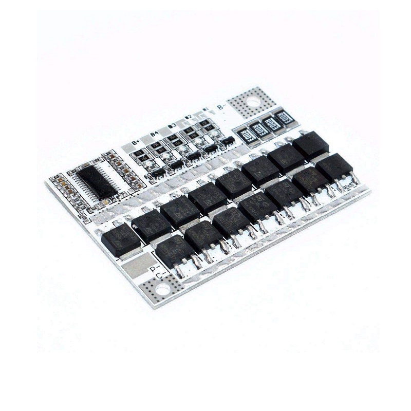
The SPIDER Automation 5S Lithium-Ion Battery Management System (BMS) is a battery protection and management board designed for battery packs consisting of five lithium-ion cells connected in series. It integrates multiple electronic protection functions to help safeguard the battery pack against abnormal charging, discharging and short-circuit conditions.
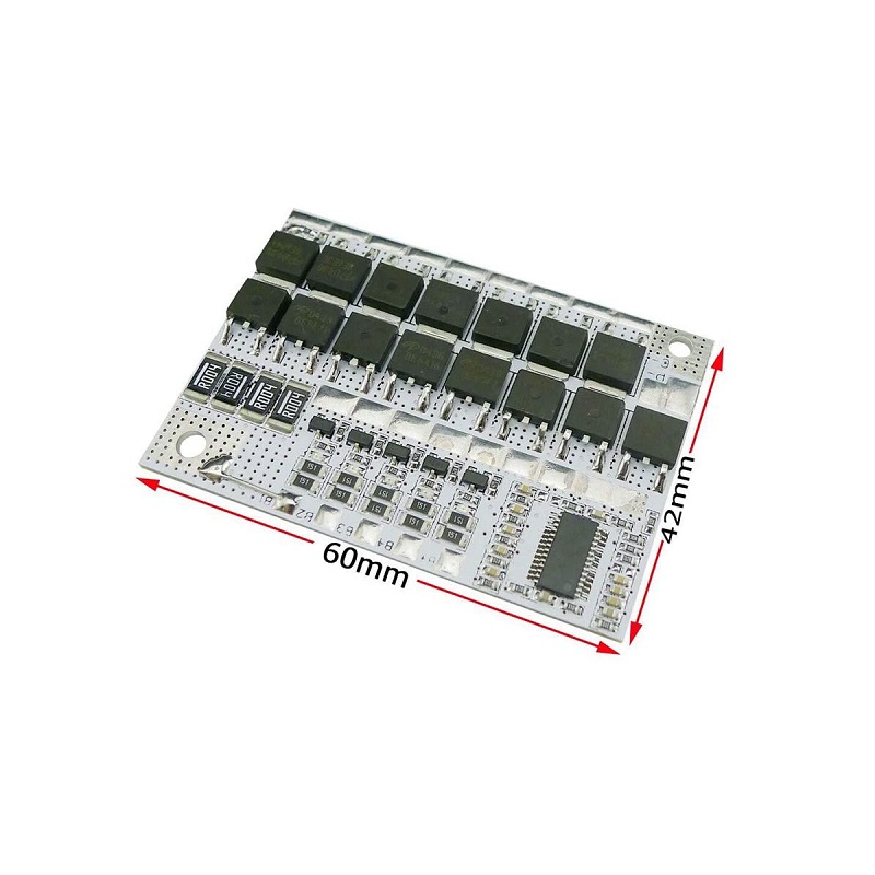
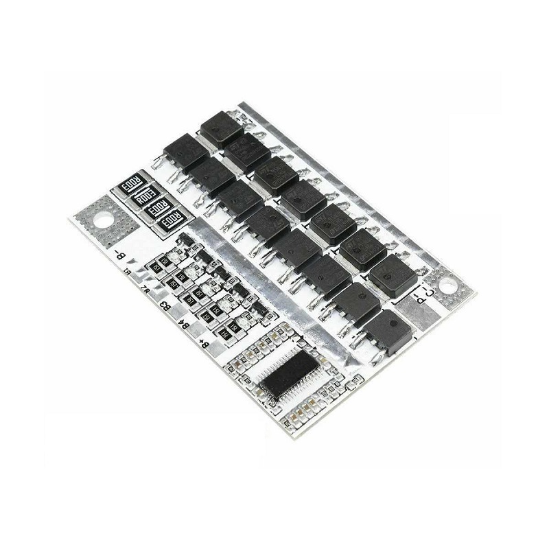
The board incorporates 15 high-power, ultra-low-resistance MOSFETs, arranged as 8 discharge MOSFETs and 7 charging MOSFETs. It supports two wiring configurations: common-port operation, with shared charging and discharging connections, and separate-port operation, with independent charging and discharging connections.
Additional functionality includes cell balancing, disconnection protection, temperature-control interface and short-circuit protection. These features make the board suitable for integrating protection and battery management functions into compatible 5S lithium-ion battery assemblies.
Technical Features & Protection Functions
- 5S Battery Configuration: Designed for five series-connected lithium-ion cells with a nominal cell voltage of 3.6V/3.7V.
- High-Power MOSFET Architecture: Uses 15 MOSFETs, including 8 discharge MOSFETs and 7 charging MOSFETs.
- Common-Port Configuration: Supports charging and discharging through a shared connection, with rated operating currents specified as 60A for charging and 60A for discharging.
- Separate-Port Configuration: Supports independent charging and discharging connections, with specified operating currents of 60A for charging and 80A for discharging.
- Overcharge Protection: Monitors individual cell voltage and provides protection when the overcharge threshold is reached.
- Over-Discharge Protection: Helps prevent individual cells from discharging below the specified protection threshold.
- Overcurrent Protection: Provides protection against excessive current conditions.
- Short-Circuit Protection: Includes a fast-response short-circuit protection function.
- Cell Balancing: Includes a balancing function for series-connected battery cells.
- Disconnection Protection: Provides a disconnection protection function within the battery protection system.
- Temperature-Control Interface: Includes a dedicated interface for temperature-related protection circuitry.
- Protection Recovery: Short-circuit protection can recover after the connected load is removed.
Electrical Configuration & Output Details
The protection board supports two connection arrangements. The appropriate configuration must be selected according to the battery pack wiring and the charging/discharging connections used in the application.
- Common-Port (Same-Port) Mode: Charging and discharging share a common electrical connection. The specified charging current is 60A and the specified discharging current is 60A.
- Separate-Port (Different-Port) Mode: Charging and discharging use separate electrical connections. The specified charging current is 60A and the specified discharging current is 80A.
- MOSFET Arrangement: Eight MOSFETs are allocated to the discharge path and seven to the charging path.
- 5S Pack Voltage: For conventional 3.6V/3.7V nominal lithium-ion cells, the series pack has a nominal voltage of approximately 18V–18.5V.
- Approximate Full-Charge Voltage: With a 4.2V-per-cell charging profile, a fully charged 5S pack reaches approximately 21V.
Important: The charging source, battery cells and protection board must have matching voltage and current specifications. The 60A and 80A figures refer to the specified charging/discharging operating-current configurations and must not be interpreted as interchangeable ratings.
Cell Voltage Protection Parameters
The board uses individual cell-voltage thresholds for overcharge and over-discharge protection. The following values define the specified protection and recovery ranges.
| Protection Parameter | Voltage / Delay |
|---|---|
| Single-Cell Overcharge Protection Voltage | 4.21–4.29V |
| Single-Cell Overcharge Recovery Voltage | 4.14–4.24V |
| Overcharge Protection Delay | 1.5–2.5 seconds |
| Single-Cell Over-Discharge Protection Voltage | 2.72–2.88V |
| Single-Cell Over-Discharge Recovery Voltage | 2.9–3.1V |
| Over-Discharge Protection Delay | 0.5–1.5 seconds |
| Short-Circuit Protection Delay | 100–600 microseconds (µs) |
| Short-Circuit Recovery | Load removal |
Applications
The 5S battery protection board can be integrated into compatible lithium-ion battery assemblies requiring cell-level voltage protection, charge/discharge management and battery balancing.
- Custom 5S Lithium-Ion Battery Packs: Protection and management circuitry for five-cell series battery assemblies.
- Portable Power Systems: Battery protection for compatible portable power equipment operating from a 5S lithium-ion pack.
- DIY Battery Pack Projects: Integration into custom-built 5S battery packs using compatible lithium-ion cells.
- Robotics Power Systems: Battery management for compatible robotic platforms and mobile robotic equipment.
- Electric Mobility Projects: Protection circuitry for suitable 5S battery-powered mobility prototypes and equipment.
- DC Backup Power Units: Battery protection in compatible low-voltage DC backup power assemblies.
- Portable Electronic Equipment: Battery management for equipment designed around a compatible 5S lithium-ion supply.
- Industrial Portable Instruments: Protection for battery-powered instruments and portable equipment using suitable 5S packs.
- Embedded Power Projects: Battery protection integration in embedded systems requiring a 5S lithium-ion power source.
- Custom Energy Storage Assemblies: Cell protection and balancing for appropriately designed 5S lithium-ion battery modules.
- High-Current DC Projects: Battery protection integration in compatible systems designed around the board’s specified current configuration.
- Electronic Prototyping: Battery management for engineering development, testing platforms and custom electronic projects.
Product Specifications
| Parameter | Specification |
|---|---|
| Product Type | Lithium-Ion Battery Management System (BMS) |
| Battery Configuration | 5S – 5 cells connected in series |
| Supported Cell Voltage Profile | 3.6V / 3.7V nominal lithium-ion cells |
| Nominal Pack Voltage | Approximately 18V–18.5V, depending on cell nominal voltage |
| Maximum Pack Charging Voltage | Approximately 21V for a 4.2V-per-cell charging profile |
| Common-Port Discharge Current | 60A |
| Common-Port Charging Current | 60A |
| Separate-Port Discharge Current | 80A |
| Separate-Port Charging Current | 60A |
| MOSFET Quantity | 15 high-power, ultra-low-resistance MOSFETs |
| Discharge MOSFETs | 8 |
| Charging MOSFETs | 7 |
| Cell Balancing | Yes |
| Overcharge Protection | Yes |
| Over-Discharge Protection | Yes |
| Overcurrent Protection | Yes |
| Short-Circuit Protection | Yes |
| Disconnection Protection | Yes |
| Temperature-Control Interface | Available |
| Short-Circuit Recovery | Load removal |
| PCB Colour | White |
| Package Contents | 1 × 5S Lithium-Ion Battery Protection Board |
Connection & Operating Recommendations
- Cell Configuration: Connect five compatible lithium-ion cells in series and follow the board’s designated cell connection sequence.
- Port Selection: Identify whether the board is configured for common-port or separate-port operation before connecting the charger and load.
- Charger Compatibility: Use a suitable 5S lithium-ion charger with a charging voltage matched to the cell chemistry and protection profile.
- Current Compatibility: Select cells, wiring, connectors and charging equipment capable of supporting the intended operating current.
- Temperature Interface: Use the temperature-control interface only with a compatible sensing arrangement specified for the board.
- Cell Matching: Use compatible cells with suitable capacity, chemistry and state of charge when assembling a series battery pack.
- Electrical Insulation: Ensure that exposed conductive areas and battery connections are properly insulated to prevent accidental short circuits.
- Operating Environment: Install the board in an enclosure that provides suitable mechanical protection, electrical clearance and heat dissipation.