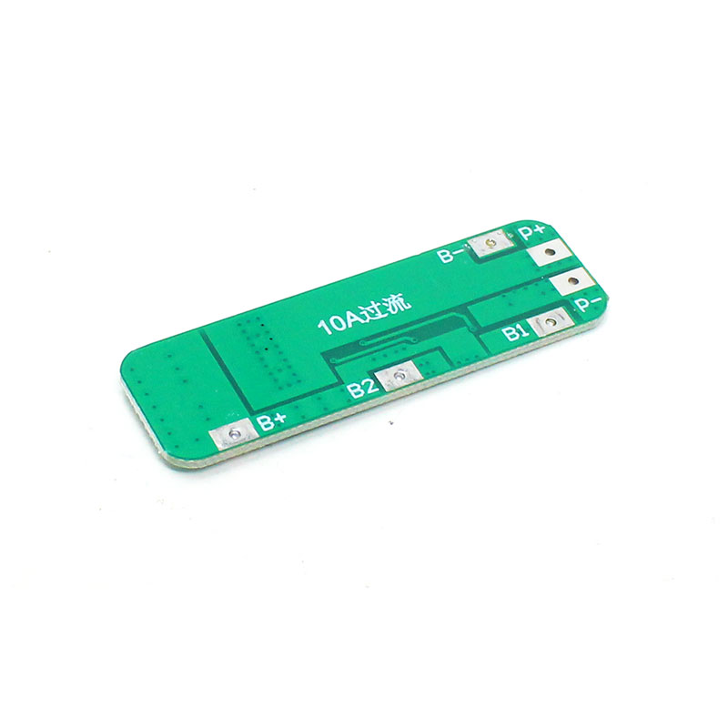

SPIDER Automation | 3S 11.1V 6A 18650 Lithium-Ion BMS Protection Board with Cell Balancing
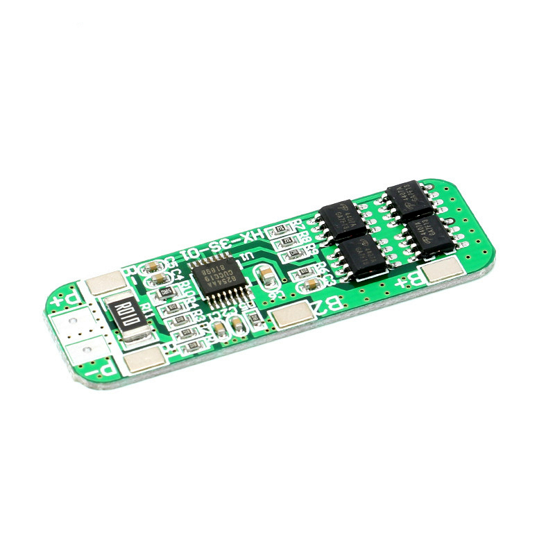
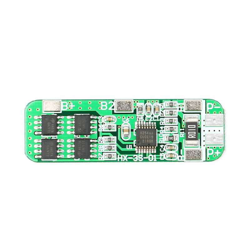
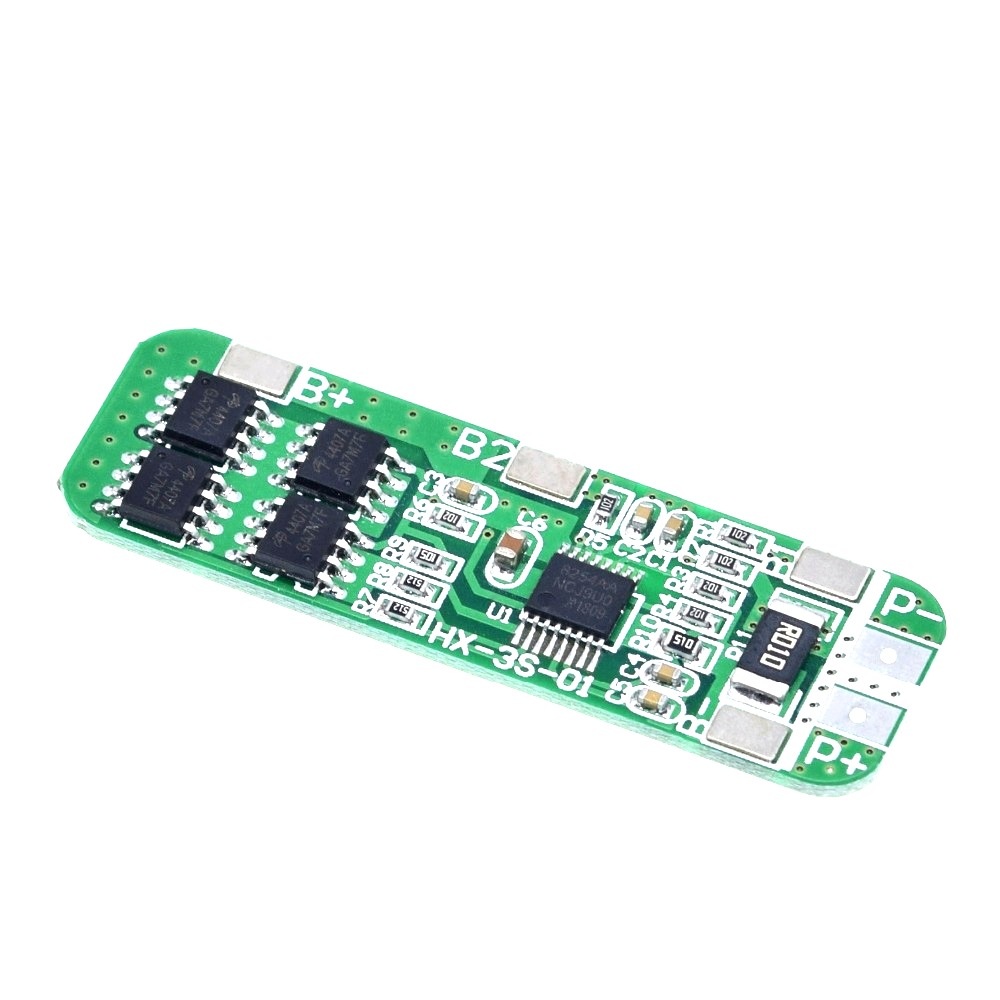
The SPIDER Automation 3S Lithium-Ion Battery Protection Board with Balancing is designed for three-cell series-connected rechargeable battery packs. It combines battery protection and cell-balancing functions to support controlled charging and discharging while helping maintain more consistent voltage levels across the individual cells.
The module incorporates an automatic recovery function and a multi-MOSFET switching arrangement. Its compact PCB construction makes it suitable for compatible battery assemblies used in portable electronics, lighting systems, backup power equipment and selected low-power motor applications.
Technical Features & Protection Functions
- Overcharge Protection: Monitors individual cell voltage and helps prevent excessive charging.
- Over-Discharge Protection: Helps prevent battery cells from being discharged below the specified protection threshold.
- Overcurrent Protection: Detects excessive current conditions and disconnects the protected circuit.
- Cell Balancing Function: Helps reduce voltage differences between individual cells during charging.
- Automatic Recovery: Supports automatic restoration of the protected circuit after certain fault conditions are removed.
- Multi-MOSFET Switching: Uses an integrated MOSFET arrangement to control battery charging and discharging paths.
- Compact Construction: Narrow PCB layout supports integration into compatible battery-pack assemblies.
Cell Balancing Function
The integrated balancing function is designed to help manage voltage differences between the individual cells in a series-connected battery pack. Cell balancing is particularly useful in multi-cell battery assemblies because differences in cell voltage can affect how effectively the pack charges and discharges.
The specified balancing current is intended for balancing operation and should not be confused with the board’s charging or discharge-current rating. The exact balancing circuit topology is not specified.
Electrical Connections & Cell Configuration
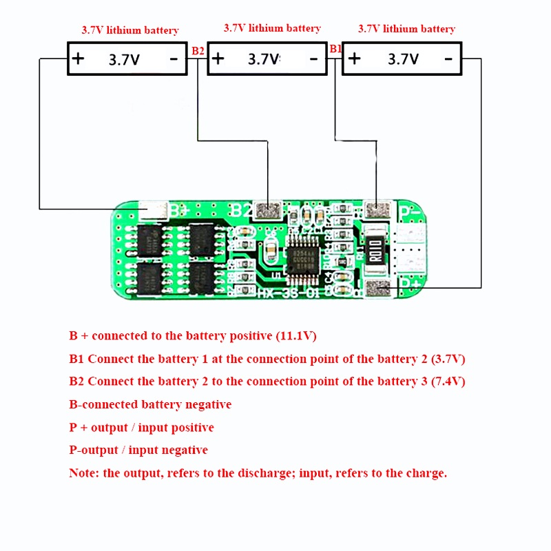
The board uses four battery connection points for the three-cell series arrangement. These terminals connect to the pack negative, intermediate cell junctions and pack positive. Correct connection order and polarity are essential for proper operation.
| Terminal | Connection Function |
|---|---|
| B− / 0V | Connect to the negative terminal of the complete battery pack. |
| B1 / 3.7V | Connect to the junction between the first and second cells. |
| B2 / 7.4V | Connect to the junction between the second and third cells. |
| B+ / 11.1V | Connect to the positive terminal of the complete battery pack. |
Important: Follow the terminal markings printed on the actual PCB. The charger and load connection points should be identified from the board markings or its wiring diagram before connecting external equipment.
Battery Pack Assembly & Compatibility
This module is intended for conventional lithium-ion battery packs assembled using three cells in series. Compatible cell formats may include cylindrical and polymer lithium-ion cells, provided their chemistry and electrical characteristics match the board’s operating requirements.
- Use three cells with compatible chemistry and voltage characteristics.
- Use cells with closely matched capacity, internal resistance and condition.
- Check individual cell voltages before connecting the cells in series.
- Ensure secure electrical connections and adequate insulation within the battery assembly.
- Consider the battery pack’s thermal conditions when selecting the operating load.
Applications
The board is suitable for compatible 3S lithium-ion battery packs used in portable equipment, low-power motor systems and rechargeable backup applications.
- Electric Drill Battery Packs: Protection and balancing for compatible low-power cordless drill battery assemblies within the board’s current limits.
- Electric Sprayers: Battery management for compatible rechargeable agricultural and portable spraying equipment.
- LED Lighting Systems: Protection for rechargeable LED lamps and portable lighting equipment.
- Massager Battery Packs: Integration into compatible rechargeable massage devices.
- Low-Power Inverters: Battery protection for suitable low-power inverter systems.
- Solar Street Light Backup: Protection for compatible rechargeable battery assemblies used in solar lighting systems.
- LED Emergency Lights: Battery management for rechargeable emergency lighting equipment.
- Monitoring Equipment: Battery protection for compatible standby power supplies used in monitoring systems.
- Portable Electronic Devices: Integration into rechargeable equipment designed around a 3S Li-ion battery pack.
- Custom Battery Projects: Protection and balancing for compatible DIY three-cell series battery assemblies.
Package Contents
- 1 × 3S 6A Lithium-Ion 18650 Battery Protection Board with Balancing
Product Specifications
| Parameter | Specification |
|---|---|
| Product Type | Lithium-Ion Battery Protection Board with Balancing |
| Battery Configuration | 3S – Three Cells in Series |
| Compatible Battery Chemistry | Conventional 3.6V / 3.7V Nominal Li-ion / LiPo |
| Compatible Cell Formats | 18650, 26650 and compatible Lithium-Polymer Cells |
| Nominal Pack Voltage | 11.1V |
| Full-Charge Pack Voltage | 12.6V |
| Recommended Charging Voltage | 12.6V CC/CV |
| Maximum Continuous Discharge Current | 6A |
| Maximum Continuous Charging Current | 6A |
| Maximum Instantaneous Current | 10A (as specified) |
| Overcharge Detection Voltage | 4.25V ± 0.025V per cell |
| Over-Discharge Detection Voltage | 2.50V ± 0.08V per cell |
| Overcurrent Protection Threshold | 10A (as specified) |
| Balancing Current | 100mA |
| Quiescent Current | Less than 30µA |
| Internal Resistance | Less than 45mΩ |
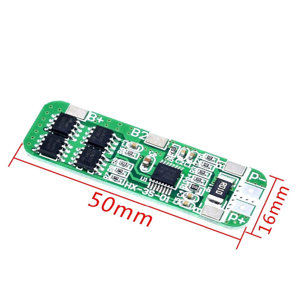
| PCB Length | 50mm |
| PCB Width | 15.5mm |
| PCB Thickness | 3mm |
| Product Weight | 3g |
Connection & Operating Recommendations
- Use a Suitable Battery Chemistry: Connect only compatible conventional lithium-ion cells. Do not use LiFePO4 cells with this board.
- Follow the Cell Connection Sequence: Connect B−, B1, B2 and B+ to the corresponding battery negative, cell junctions and battery positive points.
- Match the Cells: Use cells with closely matched voltage, capacity, internal resistance and overall condition. Avoid mixing old, damaged or mismatched cells.
- Use a Dedicated Charger: Select a regulated 3S lithium-ion CC/CV charger. The BMS is a protection and balancing module, not a standalone charger.
- Observe Current Limits: Keep the normal load and charging currents within the specified board ratings. Account for motor starting current and thermal conditions.
- Provide Adequate Cooling: Reduce the load if the board or battery assembly becomes excessively warm during operation.
- Insulate the Assembly: Protect exposed terminals and solder joints against accidental contact and short circuits.
- Check Cell Voltages: Verify individual cell-group voltages and correct wiring before putting the assembled battery pack into service.