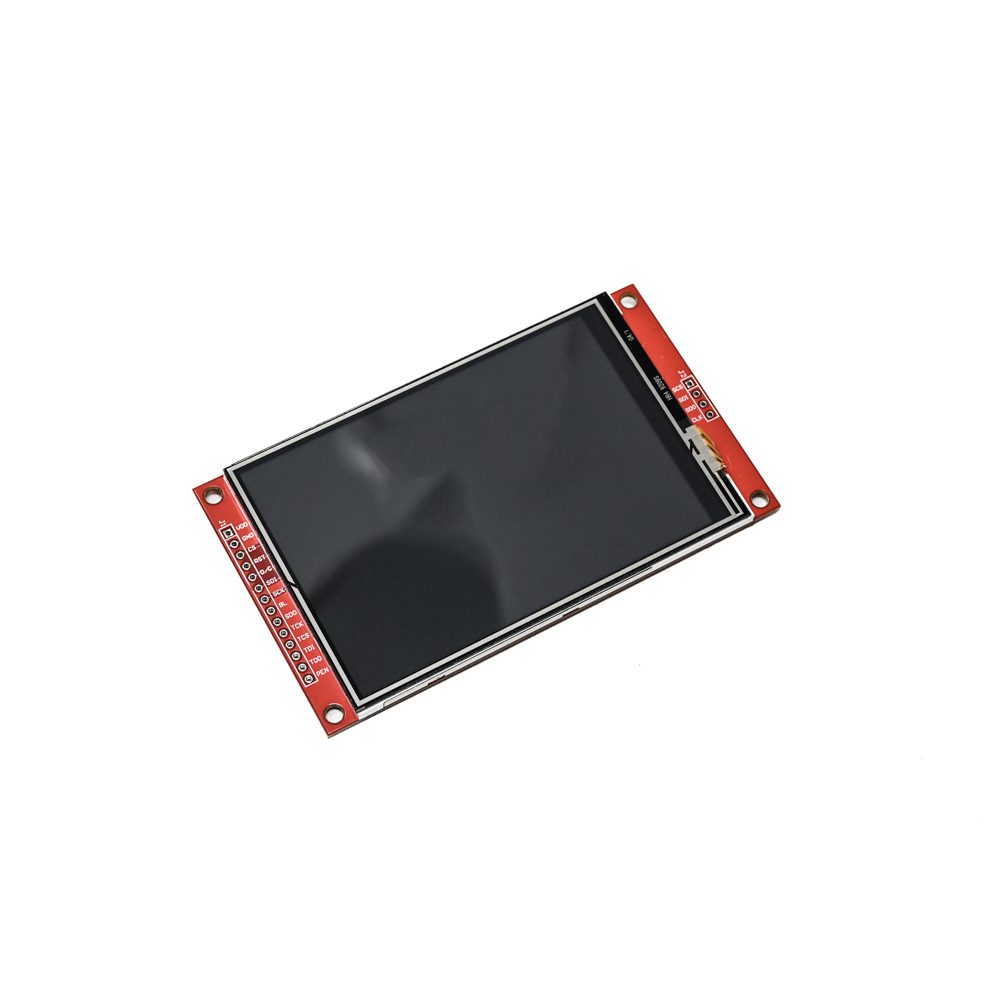
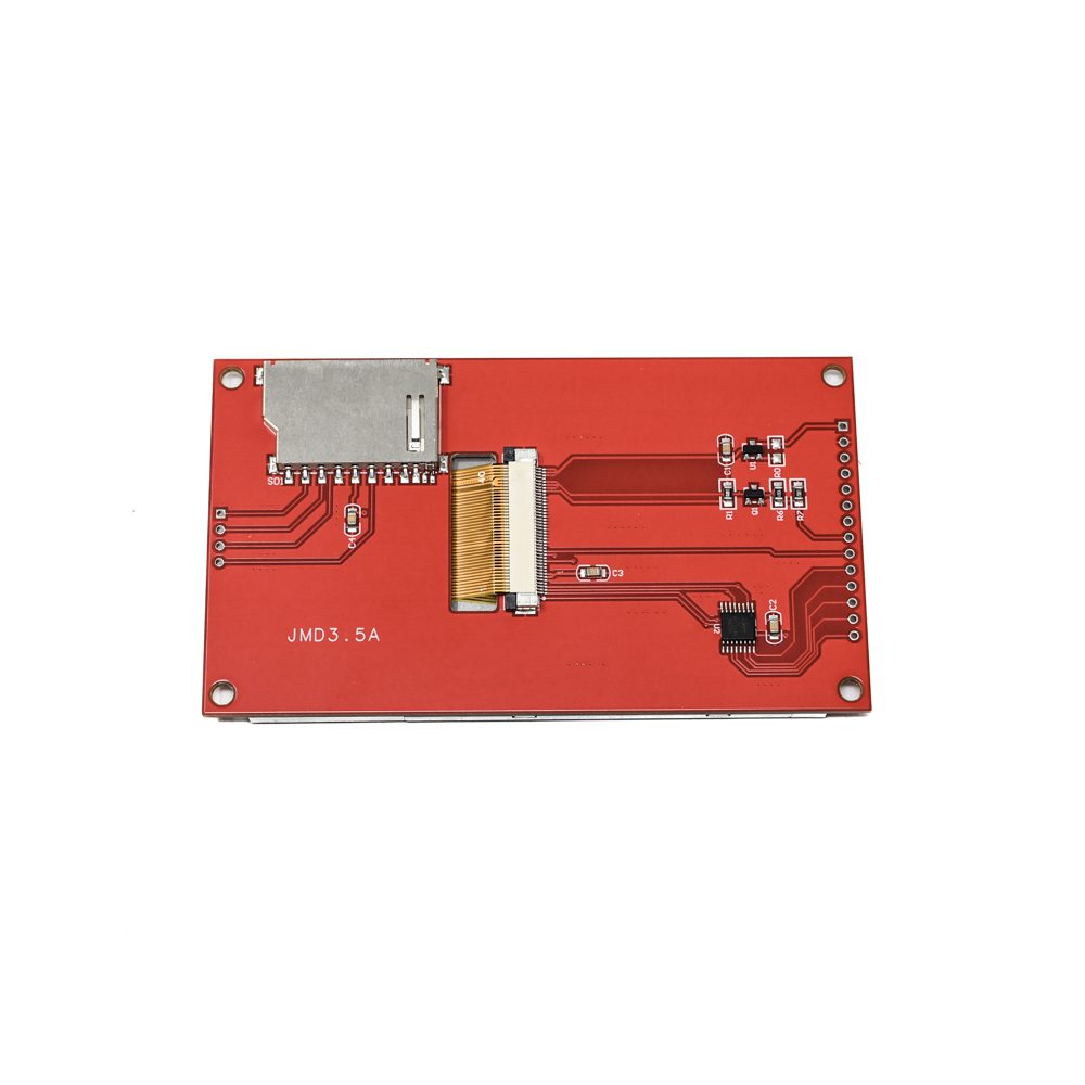
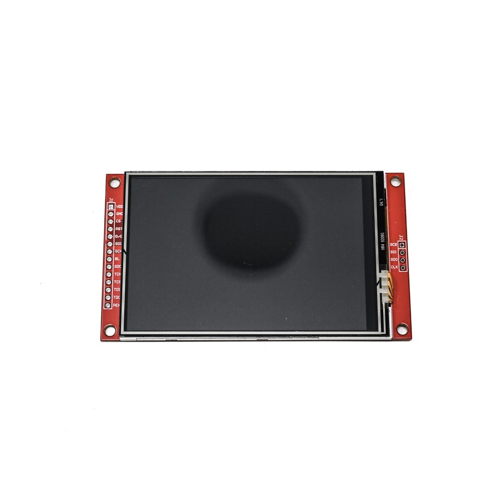

SPIDER Automation | 3.5-Inch SPI TFT LCD Resistive Touch Display Module | ILI9488 320×480 Colour Display
The SPIDER Automation 3.5-inch SPI TFT LCD Touch Display Module is designed for embedded systems requiring a colour graphical interface with touch-based user input. It uses the ILI9488 display driver and provides a 320 × 480 pixel resolution with 262K-colour depth. The TFT-LCD panel supports the presentation of text, graphical elements, icons, measurement values and equipment operating information, making it suitable for interactive electronic equipment and controller-based display applications.
The module combines a resistive touch panel with a 4-wire SPI display interface, an integrated SD card slot and dedicated BOOT and Reset buttons. Its electrical specifications include a VCC range of 3.3V–5V and 3.3V TTL logic I/O, with a separate power specification of DC 5V, 2A. The display has a 48.96 × 73.44mm active area and overall dimensions of 56.34 × 98mm, providing a compact display assembly for embedded control panels and graphical user interfaces.
Product Overview & Functional Design
The module uses a 3.5-inch Thin-Film Transistor Liquid Crystal Display (TFT-LCD) with TN panel technology. Its 320 × 480 resolution provides 153,600 pixels for rendering interface screens, text, graphical elements and numerical information. The 262K-colour display capability allows visual differentiation between interface components, status indicators and graphical content.
An integrated resistive touch panel enables user interaction through physical contact with the display surface. This allows compatible host systems to implement touch-operated menus, selection controls and interface navigation. The display and touch functions require appropriate host-side hardware and software support for their respective communication and control operations.
Technical Features & Functional Characteristics
- 3.5-Inch TFT-LCD Panel: Provides a colour display for embedded graphical interfaces and equipment information.
- ILI9488 Driver IC: Uses the ILI9488 display controller for TFT image and colour output management.
- 320 × 480 Pixel Resolution: Provides 153,600 pixels for displaying text, icons, graphics and structured interface layouts.
- 262K-Colour Display: Supports a colour depth of 262K for presenting differentiated graphical content.
- TN Display Technology: Uses a Twisted Nematic (TN) TFT-LCD panel.
- Resistive Touch Input: Incorporates a resistive touch panel for user interaction with compatible embedded applications.
- 4-Wire SPI Interface: Provides serial communication for display integration with compatible controllers.
- 50-Pin Connection Arrangement: Features a 50-pin module connection arrangement for its electrical and interface connections.
- Integrated SD Card Slot: Provides an onboard SD card slot for storage expansion in supported applications.
- BOOT Button: Includes a dedicated physical BOOT button for supported boot-related operations.
- Reset Button: Includes a physical Reset button for resetting the module or associated system, subject to the actual circuit implementation.
- 3.3V TTL Logic: Specifies 3.3V TTL logic levels for the module’s I/O interface.
- Wide VCC Specification: States a VCC supply range of 3.3V–5V, alongside a separate DC 5V, 2A power specification.
- Defined Active Display Area: Provides a 48.96 × 73.44mm active area for the visible display region.
- Compact Module Construction: Measures 56.34 × 98mm overall for integration into embedded equipment and panel assemblies.
- Operating Temperature Range: Supports a stated operating temperature range of −20°C to +60°C.
Display Resolution & Colour Rendering
The 320 × 480 pixel resolution provides a portrait-oriented display format with sufficient pixel density for structured text, graphical controls, measurement readouts and equipment status screens. With 153,600 total pixels and 262K-colour support, the display can present multiple interface elements with visual differentiation between text, backgrounds, indicators and graphical content.
The ILI9488 driver manages display output for compatible host systems. Application software can use the available display resolution to arrange menus, graphical indicators, numerical readings and other visual elements according to the requirements of the embedded system.
Resistive Touch Interface
The integrated resistive touch panel provides a physical touch-input surface for interactive applications. It can be used to implement on-screen selection, menu navigation, parameter adjustment and control commands when supported by the host controller and touch-interface software.
Touch operation requires the appropriate electrical connection and software handling for the touch interface. Display communication through SPI should not be assumed to define the touch controller interface; verify the module’s pinout and touch-controller requirements before system integration.
SPI Communication & Storage Expansion
The module supports a 4-wire SPI interface for display communication with compatible embedded controllers. Serial communication provides a practical integration approach where controller I/O availability and wiring requirements are important design considerations. The host system must support the required display-driver communication and initialisation sequence for the ILI9488.
An integrated SD card slot provides an additional storage interface for applications designed to use SD card data. Depending on the supported circuit connections and host software, this storage capability can be incorporated into systems that require external data access or file-based resources. SD card communication and display communication should be configured according to the module’s actual connection documentation.
Electrical Configuration & Control Buttons
The module specifies a VCC supply range of 3.3V–5V and 3.3V TTL logic I/O. A separate power specification states DC 5V, 2A. These electrical details should be reviewed together with the module pinout and circuit documentation before selecting the supply and connecting the display to a host controller.
Dedicated BOOT and Reset buttons are provided for supported boot and reset operations. Their exact circuit functions depend on the module’s hardware design and connection arrangement. Confirm the button connections and intended operation before incorporating them into an equipment control sequence.
Applications
The 3.5-inch SPI TFT LCD Touch Display Module is suitable for embedded equipment that requires a colour display, touch-based input and controller-driven graphical information. Its combination of TFT display output, resistive touch and SD card expansion supports a range of compact electronic interface designs.
- Embedded Control Panels: Provide graphical operating screens, parameter displays and touch-operated controls in embedded equipment.
- Industrial Monitoring Interfaces: Present equipment status, measurement values and process information through a graphical display.
- Microcontroller-Based Systems: Add colour display output and touch interaction to compatible MCU-controlled electronic designs.
- Instrumentation Equipment: Display measurement readings, operating modes, graphical indicators and instrument information.
- Automation Interface Systems: Implement touch-operated menus and graphical status screens for compatible automation controllers.
- Test and Measurement Equipment: Present test values, measurement results, interface controls and operating prompts.
- Data Monitoring Terminals: Display numerical readings, status information and graphical data generated by a host system.
- Electronic Equipment Interfaces: Provide interactive menus, configuration screens and operating information for electronic devices.
- SD Card-Based Display Systems: Support compatible applications that access SD card storage alongside graphical display functions.
- Touch-Based User Interfaces: Implement on-screen selection, navigation and parameter-entry functions through the resistive touch panel.
Package Includes
- 1 × 3.5-Inch SPI 50-Pin TFT LCD Resistive Touch Display Module with ILI9488 Driver and 320 × 480 Resolution
Product Specifications
| Parameter | Specification |
|---|---|
| Product Type | TFT LCD Touch Display Module |
| Display Size | 3.5 inches |
| Display Technology | TFT-LCD |
| Panel Type | TN (Twisted Nematic) |
| Display Driver IC | ILI9488 |
| Display Resolution | 320 × 480 pixels |
| Total Pixel Count | 153,600 pixels |
| Colour Depth | 262K colours |
| Touch Technology | Resistive |
| Display Interface | 4-Wire SPI |
| Pin Configuration | 50-pin |
| VCC Supply Range | 3.3V–5V |
| Logic I/O Level | 3.3V TTL |
| Separately Stated Power Supply | DC 5V, 2A |
| Storage Expansion | Integrated SD card slot |
| Physical Buttons | BOOT button and Reset button |
| Active Area | 48.96 × 73.44mm (W × H) |
| Module Width | 56.34mm |
| Module Height | 98mm |
| Operating Temperature | −20°C to +60°C |
Connection & Operating Recommendations
Before connecting the display, verify the 50-pin connection arrangement, supply requirements, SPI signal connections and touch-interface wiring against the module’s pinout documentation. Although the stated VCC range is 3.3V–5V, the logic I/O is specified as 3.3V TTL. Ensure that the host controller’s signal levels are compatible with the module’s logic requirements.
- Power Supply Selection: Review the stated 3.3V–5V VCC range alongside the separate DC 5V, 2A power specification. Confirm the actual module power requirements before selecting the supply.
- Logic-Level Compatibility: Use 3.3V-compatible logic signals for the specified TTL I/O. Do not assume that applying 5V to VCC makes the signal inputs 5V tolerant.
- SPI Wiring: Connect the display using the documented 4-wire SPI signal arrangement and verify the required control connections before powering the system.
- Touch Interface: Check the touch-panel controller connections and software requirements separately from the display interface.
- SD Card Integration: Verify the SD card slot’s pin connections, communication requirements and supported card configuration before implementing storage functions.
- Button Operation: Confirm the BOOT and Reset button functions from the module circuit or documentation before incorporating them into system operation.
- Mechanical Installation: Allow for the 56.34 × 98mm overall module dimensions and provide suitable clearance for the display assembly and connections.
- Temperature Conditions: Keep the module within its stated operating range of −20°C to +60°C during normal operation.
- Initial Functional Testing: Test display initialisation, SPI communication, touch response and SD card operation separately before integrating the module into the final equipment.