
SPIDER Automation | 2S 8A 18650 Li-ion Battery Protection Board | 7.4V Battery Pack
The SPIDER Automation 2S Li-ion Battery Protection Board is designed to provide essential electrical protection for two-cell series-connected lithium-ion battery packs. It monitors battery conditions during charging and discharging and provides protective switching against specified abnormal operating conditions.
With dedicated battery terminals and a common charging and load connection, this module can be integrated into compatible portable power assemblies, embedded electronics and custom battery-powered projects. Its compact PCB format supports installation in applications where available space is limited.
Technical Features & Protection Functions
- Overcharge Protection: Helps prevent individual battery cells from exceeding the specified upper voltage protection threshold.
- Over-Discharge Protection: Disconnects the protected circuit when a cell reaches the specified lower voltage protection threshold.
- Overcurrent Protection: Provides protection against excessive current conditions within the board’s specified operating limits.
- Short-Circuit Protection: Helps interrupt the protected circuit when a short-circuit condition is detected.
- Cell-Level Monitoring: Uses the battery connection points to monitor the individual cell sections of the series pack.
- Low Static Consumption: Designed for low standby current draw when the battery pack is not actively powering a load.
Electrical Configuration & Output Details
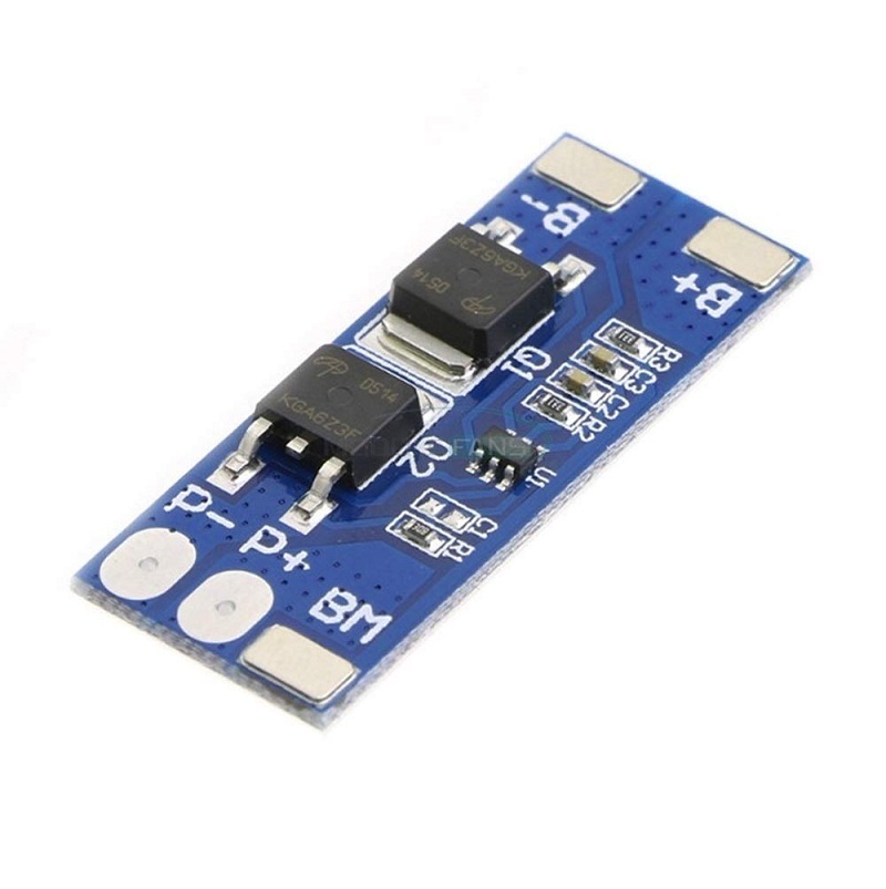
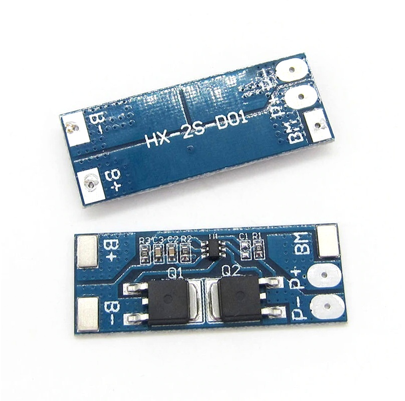
This module uses a common-port charging and discharging arrangement. The P+ and P− terminals serve as the shared positive and negative connections for the charger and external load. The battery-side terminals connect directly to the two-cell series assembly.
For conventional 3.6V/3.7V nominal lithium-ion cells, a 2S battery pack has a nominal pack voltage of 7.2V/7.4V and a full-charge voltage of 8.4V. Use a compatible 2S lithium-ion CC/CV charger with an 8.4V charge-voltage limit. This protection board does not replace the external battery charger.
Battery Connection Details
The board provides dedicated connection points for the battery pack and the external charging/load circuit. Correct terminal identification and cell polarity are essential before connecting the module.
- B+: Positive terminal of the complete 2S battery pack.
- B−: Negative terminal of the complete 2S battery pack.
- MB: Midpoint connection between the two series-connected battery cells.
- P+: Common positive connection for the charger and external load.
- P−: Common protected negative connection for the charger and external load.
Connection guidance: Connect B− to the negative end of the first cell, MB to the junction between the two cells, and B+ to the positive end of the second cell. Connect the charger and load through P+ and P−. Follow the actual PCB markings and connection diagram when wiring the board.
Functional Advantages
- Compact Integration: Suitable for battery-powered equipment with limited internal mounting space.
- Shared Charging and Load Port: Simplifies external wiring by using a common protected connection.
- Series-Cell Protection: Provides protection for the individual cell sections within a 2S battery assembly.
- Reduced Standby Consumption: Low static current helps limit unnecessary battery drain during idle periods.
- DIY Battery Pack Integration: Can be incorporated into compatible custom-built lithium-ion battery assemblies.
Applications
This protection board can be used in compatible 2S lithium-ion battery packs where the connected load remains within the board’s electrical limits.
- Portable Electronic Equipment: Battery protection for compatible portable devices.
- DIY 18650 Battery Packs: Protection circuitry for custom two-cell series battery assemblies.
- Embedded Electronics: Battery pack integration in compact electronic projects.
- Low-Power LED Systems: Battery protection for compatible LED lighting assemblies.
- Portable Instrumentation: Power protection for suitable battery-operated measuring and testing equipment.
- Wireless Sensor Projects: Battery pack protection for low-power sensor nodes.
- Microcontroller Projects: Protected battery supply for compatible embedded development systems.
- Portable Communication Devices: Battery protection for suitable low-current communication electronics.
- Small Backup Power Assemblies: Protection for compatible compact backup battery packs.
- Custom Electronic Enclosures: Integration into space-constrained battery-powered product designs.
Package Contents
- 1 × 2S 8A 18650 Li-ion Battery Protection Board
Product Specifications
| Parameter | Specification |
|---|---|
| Product Type | Lithium-ion Battery Protection Board / BMS |
| Battery Configuration | 2S (2 cells connected in series) |
| Compatible Battery Chemistry | Conventional Li-ion / LiPo, 3.6V–3.7V nominal cells |
| Nominal Pack Voltage | 7.2V / 7.4V, depending on cell nominal voltage |
| Full-Charge Pack Voltage | 8.4V |
| Recommended Charger Voltage | 8.4V CC/CV for conventional 4.2V-per-cell Li-ion batteries |
| Maximum Working Current | 8A |
| Limit Instantaneous Current | 10A |
| Overcharge Voltage Range per Cell | 4.25V–4.35V ±0.05V (listed protection range) |
| Discharge Voltage Range | 2.5V–3.0V ±0.05V per cell (listed protection range) |
| Static Current | <10µA |
| Internal Resistance | <300mΩ |
| Protection Functions | Overcharge, over-discharge, overcurrent and short-circuit protection |
| Connection Configuration | B+, B−, MB, P+, P− |
| Working Temperature | −40°C to +50°C |
| Storage Temperature | −40°C to +80°C |
| PCB Length | 40.7mm |
| PCB Width | 16mm |
| PCB Height / Thickness | 4mm |
| Board Weight | 6g |
| PCB Colour | Blue or Green |
Connection & Operating Recommendations
- Use Compatible Cells: Assemble the pack using two compatible lithium-ion cells with matching chemistry, voltage characteristics, capacity and condition.
- Check Cell Polarity: Identify the battery negative, cell midpoint and battery positive connections carefully before soldering.
- Use the Correct Charger: Select a dedicated 2S Li-ion CC/CV charger with the correct full-charge voltage. Do not use a 3S charger or a charger intended for LiFePO4 cells.
- Observe Current Limits: Keep the continuous load and charging arrangement within the board’s specified electrical limits. The instantaneous rating must not be treated as a continuous current rating.
- Check Load Compatibility: Avoid high-starting-current motors and other loads that may exceed the board’s operating capability.
- Do Not Use with LiFePO4: This board is intended for conventional lithium-ion chemistry and is not suitable for lithium iron phosphate battery packs.
- Insulate Exposed Connections: Prevent solder joints and battery terminals from contacting conductive surfaces or the enclosure.
- Verify Wiring Before Power-Up: Check all terminal connections and cell voltages before connecting the charger or load.