
SPIDER Automation | MY6812 24V 150W Brushed DC Motor | 2750RPM Chain-Drive Motor with 9T #25 Sprocket
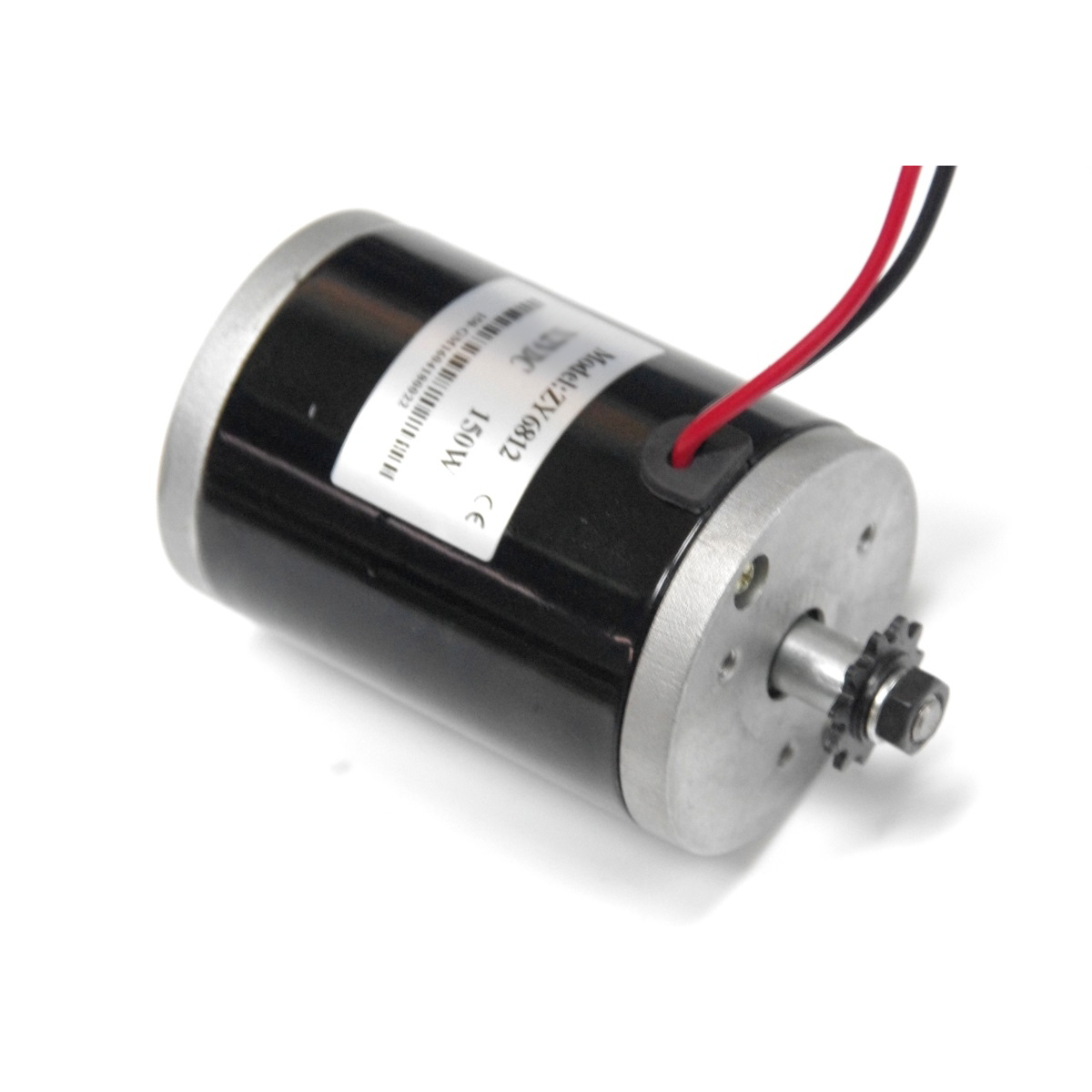
The SPIDER Automation MY6812 24V 150W Brushed DC Motor is designed for compact electric drive systems used in compatible scooters, small electric carts, bicycle projects and robotics applications. It operates on a 24V DC supply and has a listed operating power of 150W with a rated rotational speed of 2750RPM. Its brushed DC construction is intended for use with a suitable brushed motor controller.
This chain-drive version is supplied with a 9-tooth sprocket for #25 chain. The shaft arrangement is described as an 8mm D-cut profile with circlip retention for the fitted shaft component. The motor also features ball-bearing construction. Its listed no-load current is 1,000mA, loaded speed range is 2600–3000RPM and efficiency rating is 0.7. These characteristics provide useful references when selecting the motor for a compatible mechanical and electrical drive system.
Product Overview & Motor Construction
The MY6812 is a brushed DC motor intended for low-voltage electric drive applications. Its 24V operating voltage and 150W power rating make it suitable for compatible small vehicle and equipment systems. As a brushed motor, it requires a controller designed for brushed DC motor operation.
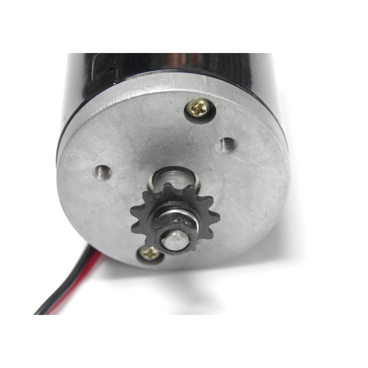
This version has a chain-drive output with a pre-fitted 9-tooth sprocket for #25 chain. The 8mm D-cut shaft and circlip-retained arrangement provide a defined mechanical interface for compatible components. Ball-bearing construction is also identified in the product description.
Technical Features & Performance Characteristics
- MY6812 Model: Identifies the motor model for selecting compatible replacement motors and drive-system components.
- Brushed DC Motor Technology: Uses a brushed commutation arrangement and requires a suitable brushed DC controller.
- 150W Operating Power: Specified for compact electric drive applications requiring a 150W motor.
- 24V DC Operating Voltage: Designed for compatible 24V electrical systems.
- 2750RPM Rated Speed: Provides a rotational speed reference for selecting the chain reduction ratio and driven load.
- 2600–3000RPM Loaded Speed Range: Listed as the loaded rotational speed range in the supplied specifications.
- 9-Tooth Drive Sprocket: Supplied with a 9T sprocket for compatible #25 chain.
- 8mm D-Cut Shaft: Provides a shaft interface with an 8mm nominal dimension and a flat-sided D profile.
- Circlip Retention: The source describes a circlip-retained shaft component that can be released for removal where the assembly permits.
- Ball-Bearing Construction: Identified in the source description for the motor’s rotating assembly.
- No-Load Current: Listed at 1,000mA, equivalent to 1A under no-load conditions.
- Efficiency Rating: Supplier-listed value of 0.7, equivalent to 70%.
Chain-Drive Output & Sprocket Compatibility
The motor is supplied with a 9-tooth sprocket intended for #25 chain. The sprocket transfers motor rotation to a compatible driven sprocket through a chain-drive arrangement. The final output speed and torque at the driven shaft or wheel depend on the selected sprocket ratio and the mechanical load.
Use a matching #25 chain and driven sprocket. Chain pitch, roller dimensions, sprocket tooth profile and alignment must be compatible. Do not assume that this sprocket is interchangeable with 25H, 410, 420 or T8F chain components; these are different chain designations.
Shaft Design & Mechanical Interface
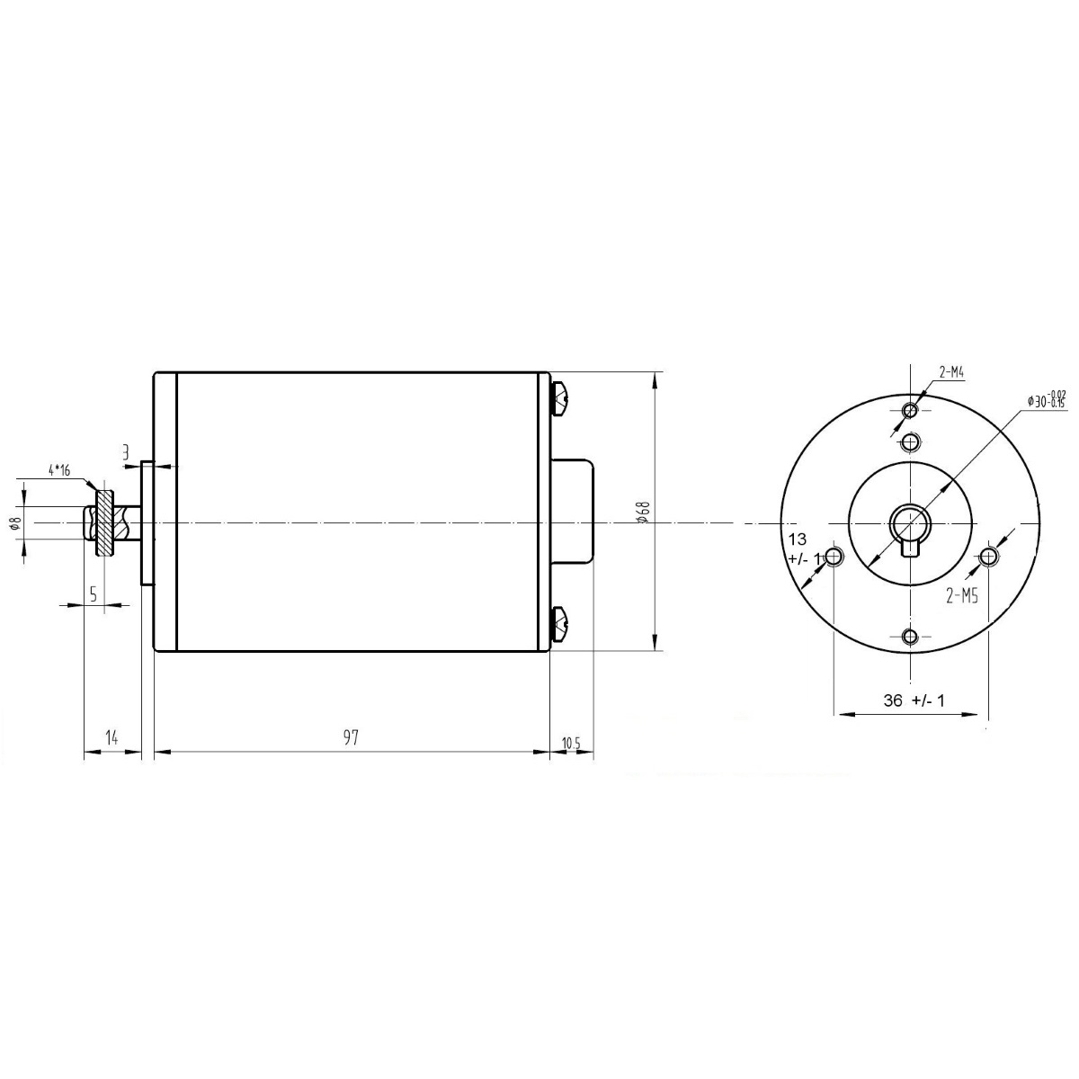
The motor is described with an 8mm D-cut shaft. The D-shaped profile provides a flat reference surface for compatible mechanical components. The source also describes a circlip-retained arrangement, allowing the fitted shaft component to be removed after the retaining clip is correctly released.
Before installation, check the mating component’s bore, D-flat geometry, axial position and retention method. Do not assume that every 8mm pulley, sprocket or coupling will fit this shaft correctly. The supplied product description identifies a 9T chain sprocket; it does not establish that a separate belt pulley is included.
Electrical Configuration & Controller Compatibility
This motor is specified for 24V DC operation and uses brushed DC motor technology. It must be paired with a compatible brushed motor controller suitable for the motor’s electrical requirements. A BLDC controller is not an interchangeable substitute because brushless motors use a different commutation arrangement.
The listed no-load current is 1,000mA (1A). This value describes no-load operation and should not be used as the motor’s loaded current requirement. The supplied description does not establish wire colours, connector type or terminal polarity. Follow the motor and controller wiring documentation when connecting the unit.
Applications
The MY6812 motor can be used in compact electric drive systems where its 24V supply, 150W rating, shaft arrangement and #25 chain-drive output are suitable for the intended equipment.
- Electric Scooter Projects: Drive motor integration in compatible small scooters designed for a 24V brushed DC motor.
- Small Electric Carts: Use in compact electric carts with a matching motor mount and chain-drive transmission.
- Electric Bicycle Projects: Motor integration in compatible custom bicycle drive systems designed around the MY6812 motor and #25 chain interface.
- Robotics Platforms: Use in mobile robotics systems requiring a compact brushed DC motor and mechanical chain transmission.
- Chain-Driven Mechanisms: Power transmission for compatible mechanisms using a #25 chain and matching driven sprocket.
- Small Electric Vehicle Prototypes: Integration in engineering prototypes designed around the motor’s voltage and power rating.
- Replacement Motor Installations: Replacement of an existing MY6812 motor when the electrical, shaft and mounting interfaces match.
- Educational Engineering Builds: Use in supervised motor-control and mechanical-drive demonstrations.
- Compact Drive Assemblies: Motor integration in equipment requiring a 24V brushed motor with a pre-fitted chain sprocket.
- Custom Mechanical Projects: Use in compatible projects requiring a D-cut shaft and chain-drive output.
Package Includes
- 1 × MY6812 24V 150W Brushed DC Motor with 9-Tooth #25 Chain Sprocket
Product Specifications
| Parameter | Specification |
|---|---|
| Product Type | Electric DC Motor |
| Model Number | MY6812 |
| Motor Type | Brushed DC Motor |
| Operating Voltage | 24V DC |
| Operating Power | 150W |
| Rated Speed | 2750RPM |
| Loaded Speed Range | 2600–3000RPM (listed) |
| No-Load Current | 1,000mA (1A) |
| Efficiency | 0.7 (70%) |
| Drive Configuration | Chain Drive |
| Supplied Sprocket | 9 Teeth (9T) |
| Chain Compatibility | #25 Chain |
| Shaft Type | D-Cut Shaft |
| Shaft Size | 8mm nominal dimension |
| Shaft Retention | Circlip-retained arrangement, as described |
| Bearing Construction | Ball-bearing construction, as described |
| Controller Type | Compatible 24V brushed DC motor controller |
| Package Quantity | 1 Motor Assembly |
Connection & Operating Recommendations
Before powering the motor, confirm that the battery and controller are suitable for a 24V brushed DC motor and that the mechanical drivetrain matches the supplied #25 chain sprocket and shaft arrangement.
- Use a Brushed Motor Controller: Select a controller designed for brushed DC motors and suitable for the motor’s 24V operating configuration.
- Match the Power Supply: Use a compatible 24V DC battery system and ensure that the controller and wiring are selected for the motor’s loaded operating requirements.
- Account for Loaded Current: Do not size the controller or battery using the 1A no-load current figure. Select components for the motor’s actual loaded and startup current requirements.
- Match the #25 Chain: Use a compatible #25 chain and driven sprocket. Do not substitute a different chain series based only on visual similarity.
- Check Sprocket Alignment: Align the motor sprocket and driven sprocket to avoid uneven chain loading, excessive wear and derailment.
- Inspect the D-Cut Shaft: Confirm that the mating component matches the 8mm D-cut profile and has suitable axial retention.
- Handle the Circlip Correctly: Use suitable circlip tools when removing or refitting the retaining clip. Ensure the component is securely retained before operation.
- Secure the Motor Mount: Use a rigid mounting arrangement appropriate for the motor’s torque reaction and the equipment’s operating conditions.
- Verify Electrical Connections: Follow the correct wiring documentation for terminal polarity and controller connections rather than assuming wire functions from cable appearance.
- Perform a Controlled Initial Test: Check motor rotation, chain tracking, mechanical clearance and controller response during an initial unloaded test.