
SPIDER Automation | 2204 260KV Brushless Gimbal Motor | 12–24V Camera Stabilisation Motor for Multi-Rotor Systems
Product Overview & Motor Design
The SPIDER Automation 2204 260KV Brushless Gimbal Motor is a compact brushless motor developed for camera stabilisation assemblies used in multi-rotor aerial platforms and other motorised camera positioning systems. Its primary function is to provide controlled rotational movement to a gimbal axis, allowing the connected control electronics to adjust camera orientation and compensate for unwanted movement of the supporting platform.
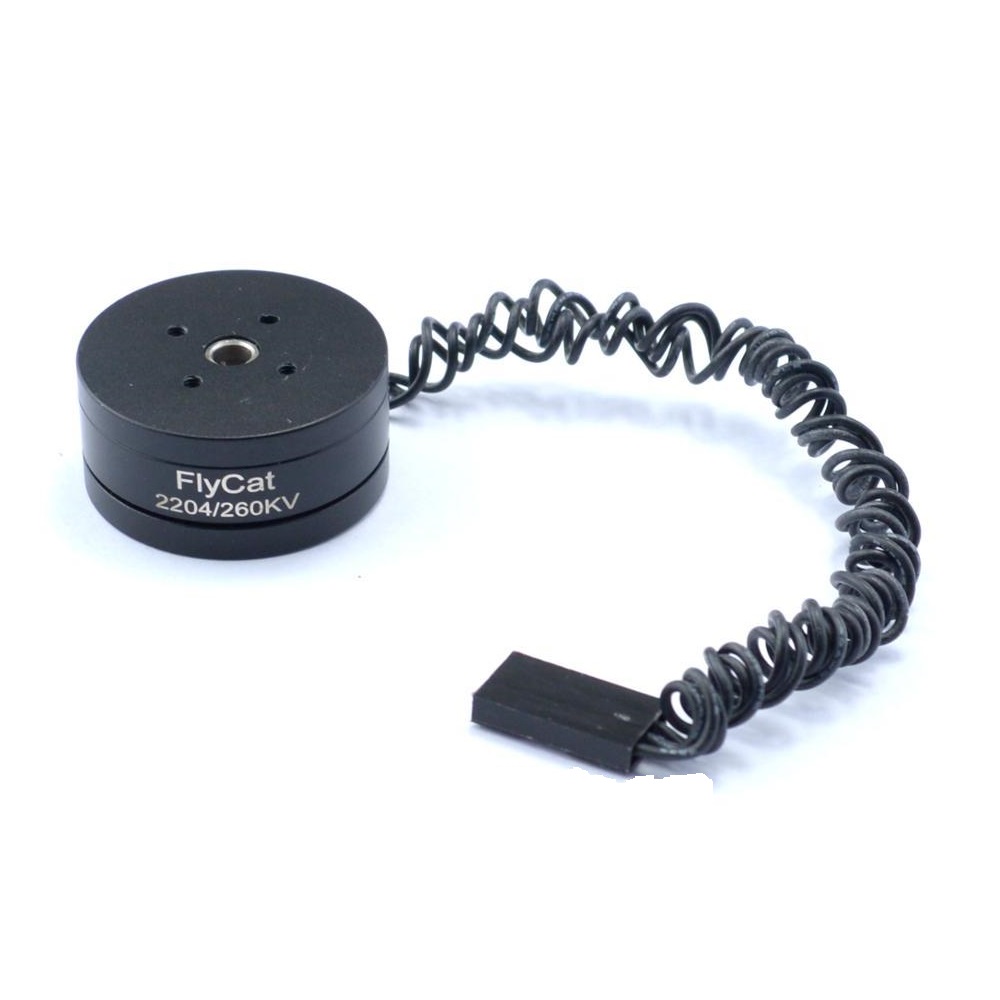
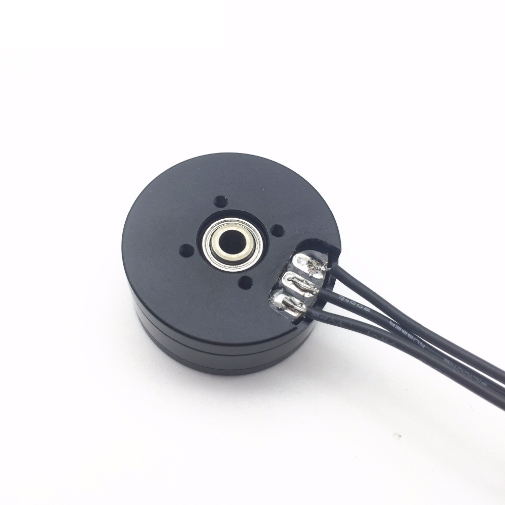
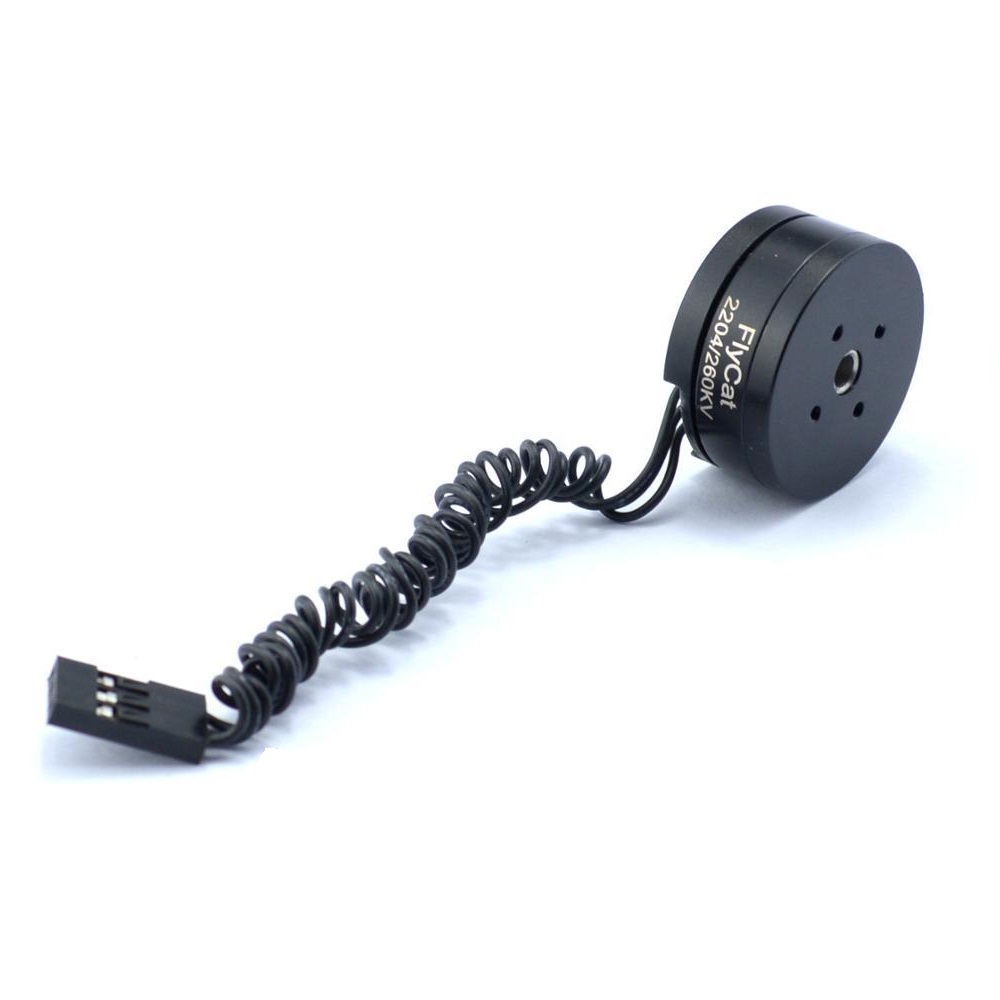
The motor features a pre-wound construction, 260KV winding specification and preloaded bearing arrangement. Its compact 28 × 28 × 13 mm external profile is intended for integration into appropriately designed lightweight gimbal structures. A flexible 30 cm cable with a Futaba/JR-style servo connector provides a ready-fitted electrical interface for compatible gimbal controllers. The stated camera payload application range is approximately 100–200 g, making this configuration relevant to lightweight action-camera stabilisation systems.
With a specified working voltage range of 12–24V, the motor is intended to operate as part of a compatible brushless gimbal control system. Motor selection should consider the complete stabilisation assembly, including camera mass, centre of gravity, gimbal geometry and controller capability.
Technical Features & Performance Characteristics
- 260KV Brushless Winding: The KV rating represents the motor’s rotational speed constant under specified electrical conditions. It is an important selection parameter when matching the motor with a gimbal controller and operating voltage. Actual operating speed depends on the controller’s drive method and the mechanical load.
- Pre-Wound Motor Configuration: The motor is supplied with its winding already installed, eliminating the requirement for winding work during normal gimbal assembly. This allows the integration process to focus on motor mounting, cable routing, mechanical balancing and controller configuration.
- Compact 2204 Format: The motor’s stated external dimensions of 28 × 28 × 13 mm provide a compact profile for lightweight gimbal structures. The reduced height is relevant when designing assemblies where available motor clearance and overall gimbal dimensions are important.
- Preloaded Bearing Arrangement: Preloaded bearings support controlled rotational movement and help minimise unwanted mechanical play. In camera stabilisation assemblies, mechanical looseness can affect positioning consistency, making the bearing arrangement an important part of the motor’s mechanical design.
- 12–24V Working Voltage: The specified operating range provides flexibility when selecting a compatible gimbal power system. The motor must be driven through suitable control electronics that support its electrical requirements.
- Flexible Cable Construction: The 30 cm cable provides routing allowance within the gimbal structure. Cable flexibility is particularly important in moving camera assemblies because excessive cable stiffness or tension can introduce unwanted resistance during angular movement.
- Servo-Style Electrical Connector: The fitted Futaba/JR-style connector provides a convenient connection interface for supported gimbal controllers. It reduces the need for separate connector installation, although electrical pin compatibility must still be verified.
- Bidirectional Rotation: The motor is specified for operation in both rotational directions. Actual direction control depends on the connected controller’s electrical drive arrangement and configuration.
- Low-Mass Construction: The stated 26 g motor weight is relevant when calculating the moving mass of a compact gimbal assembly. Total gimbal weight and camera balance should be considered during system design.
Electrical Configuration & Controller Integration
The 2204 260KV is intended for operation through a compatible brushless gimbal controller. The controller manages the motor’s electrical drive to produce controlled angular movement of the camera-supporting gimbal axis. This differs from conventional brushless propulsion arrangements, where the motor is primarily operated to generate continuous rotational output for a propeller or other load.
The specified working voltage is 12–24V, with a listed maximum operating current of 600mA. These electrical specifications should be considered when selecting the controller and power arrangement. The controller must support the motor’s electrical characteristics and the intended gimbal operating mode. The listed current should not be treated as a complete power-system sizing value without the controller’s operating conditions and measurement basis.
A 30 cm flexible cable terminates in a Futaba/JR-style servo connector. This provides a convenient physical interface, but connector shape alone does not establish pin assignment or electrical compatibility. Verify the controller’s motor-output arrangement and connection documentation before applying power.
Mechanical Construction, Mounting & Gimbal Balancing
The motor has a stated external profile of 28 mm length × 28 mm width × 13 mm height, making it suitable for compact gimbal structures designed around these dimensions. Its preloaded bearing arrangement supports controlled rotation, while its lightweight construction helps limit the mass added to the moving camera assembly.
Mechanical balancing is essential when integrating a gimbal motor. The camera should be positioned so that its centre of gravity is appropriately aligned with the gimbal’s rotational axes. An unbalanced camera can impose additional load on the motor and may reduce stabilisation quality or increase the demands placed on the controller.
The 30 cm flexible cable should be routed with sufficient slack to accommodate the complete movement range of the gimbal. Cable tension, interference with the frame or contact with moving components can introduce unwanted mechanical resistance. The motor’s mounting interface and available clearance should also be checked against the selected gimbal frame before installation.
Camera Compatibility & Applications
The 2204 260KV configuration is intended for compact camera stabilisation systems with a stated payload application range of approximately 100–200 g. This range provides a reference for lightweight camera selection, including GoPro-class cameras. Actual compatibility depends on camera dimensions, centre of gravity, mounting position, gimbal arm geometry and the capabilities of the selected controller.
- GoPro-Class Camera Gimbals: For lightweight action-camera stabilisation assemblies designed around the motor’s intended payload application range.
- Multi-Rotor Aerial Camera Systems: For gimbal assemblies integrated into multi-rotor platforms to provide controlled camera orientation during aerial operation.
- Brushless Camera Stabilisation: For single-axis or multi-axis gimbal systems that use brushless motors and dedicated stabilisation controllers.
- Aerial Photography Platforms: For camera positioning systems used in aerial image capture where controlled angular adjustment is required.
- Aerial Video Recording Systems: For compatible gimbal arrangements intended to maintain camera orientation while the supporting aerial platform moves.
- Compact Motorised Camera Mounts: For lightweight camera mounting structures requiring controlled rotational positioning.
- Pan and Tilt Camera Assemblies: For custom motorised positioning systems designed around compatible brushless gimbal control electronics.
- UAV Camera Integration Projects: For engineering applications involving the mechanical and electrical integration of lightweight cameras into aerial platforms.
Package Includes
- 1 × 2204 260KV Brushless Gimbal Motor
Product Specifications
| Parameter | Specification |
|---|---|
| Product Type | Brushless Gimbal Motor |
| Model | 2204 |
| Motor KV Rating | 260KV (RPM/V) |
| Motor Configuration | Brushless, pre-wound |
| Working Voltage | 12–24V |
| Maximum Operating Current | 600mA |
| Rotation Direction | Both directions |
| Stated Camera Payload Range | Approximately 100–200 g |
| Connector Type | Servo-style Futaba/JR |
| Cable Length | 30 cm |
| Length | 28 mm |
| Width | 28 mm |
| Height | 13 mm |
| Bearing Arrangement | Preloaded bearings |
| Product Weight | 26 g |
Connection & Operating Recommendations
For reliable operation, the motor should be integrated with a compatible brushless gimbal controller and a mechanically balanced camera assembly. Correct electrical matching and cable management are particularly important because the motor operates as part of a coordinated stabilisation system rather than as an independent propulsion unit.
- Verify Operating Voltage: Keep the motor supply arrangement within the stated 12–24V working range and ensure that the connected controller supports the selected supply voltage.
- Check Current Compatibility: Consider the listed 600mA maximum operating current when reviewing controller compatibility. Confirm the controller’s current-handling capability and operating conditions before installation.
- Match the Gimbal Controller: Use brushless gimbal control electronics designed to support the motor’s electrical characteristics and intended stabilisation function.
- Verify Connector Wiring: Confirm the Futaba/JR connector pin arrangement against the controller documentation. Do not connect solely on the basis of connector appearance.
- Balance the Camera Mechanically: Position the camera and adjust the gimbal structure to minimise imbalance before controller calibration and operation.
- Secure Cable Routing: Provide sufficient cable slack throughout the gimbal’s movement range and prevent the cable from pulling against the motor or obstructing moving parts.
- Check Payload Suitability: Evaluate the complete camera assembly, including weight, dimensions and centre of gravity, against the gimbal’s mechanical design and controller capability.
- Follow Controller Calibration: Perform motor configuration, calibration and stabilisation tuning according to the instructions provided with the selected gimbal controller.