
SPIDER Automation | 1S 5MOS 18650 Lithium-Ion Battery Protection Board | Single-Cell Battery Protection Circuit
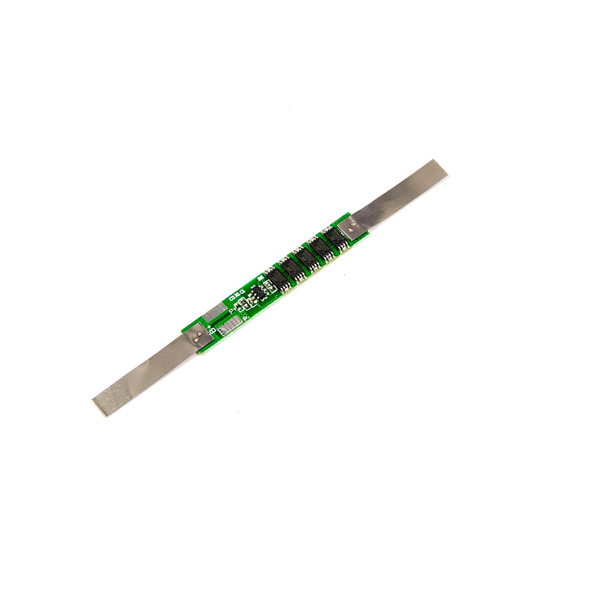
The SPIDER Automation 1S 5MOS 18650 Lithium-Ion Battery Protection Board is designed to provide essential electrical protection for single-cell lithium-ion battery packs. It uses a 5-MOSFET switching configuration to control the electrical connection between the battery and its external circuit under specified operating conditions.
Lithium-ion cells require controlled charging and discharging to help prevent damaging operating conditions. This protection board is designed to monitor battery voltage and current-related conditions and provide protection against overcharging, excessive discharge, overcurrent and short circuits.
The board supports a 1S lithium-ion battery configuration, typically using one 18650 cell or multiple cells connected in parallel to form a single battery group. It provides separate battery-side and protected-output terminals, making it suitable for integration into compact battery-powered electronic projects and equipment.
Technical Features & Circuit Construction
- Single-Cell Protection Architecture: Designed for 1S lithium-ion battery packs with a nominal voltage of 3.7V and a typical full-charge voltage of 4.2V.
- Five-MOSFET Configuration: Incorporates five MOSFETs in the battery protection switching circuit.
- Overcharge Protection: Monitors battery voltage against the specified overcharge detection threshold of 4.25V ± 0.05V.
- Over-Discharge Protection: Detects battery voltage reduction at the specified threshold of 2.45V ± 0.1V.
- Overcurrent Protection: Includes an overcurrent detection function with a specified detection value of 7.5A.
- Short-Circuit Protection: Designed to interrupt the protected circuit under short-circuit conditions.
- Protected Output Path: Uses P+ and P− terminals for the external protected battery connection.
- Dedicated Battery Connections: Provides B+ and B− terminals for direct connection to the battery pack.
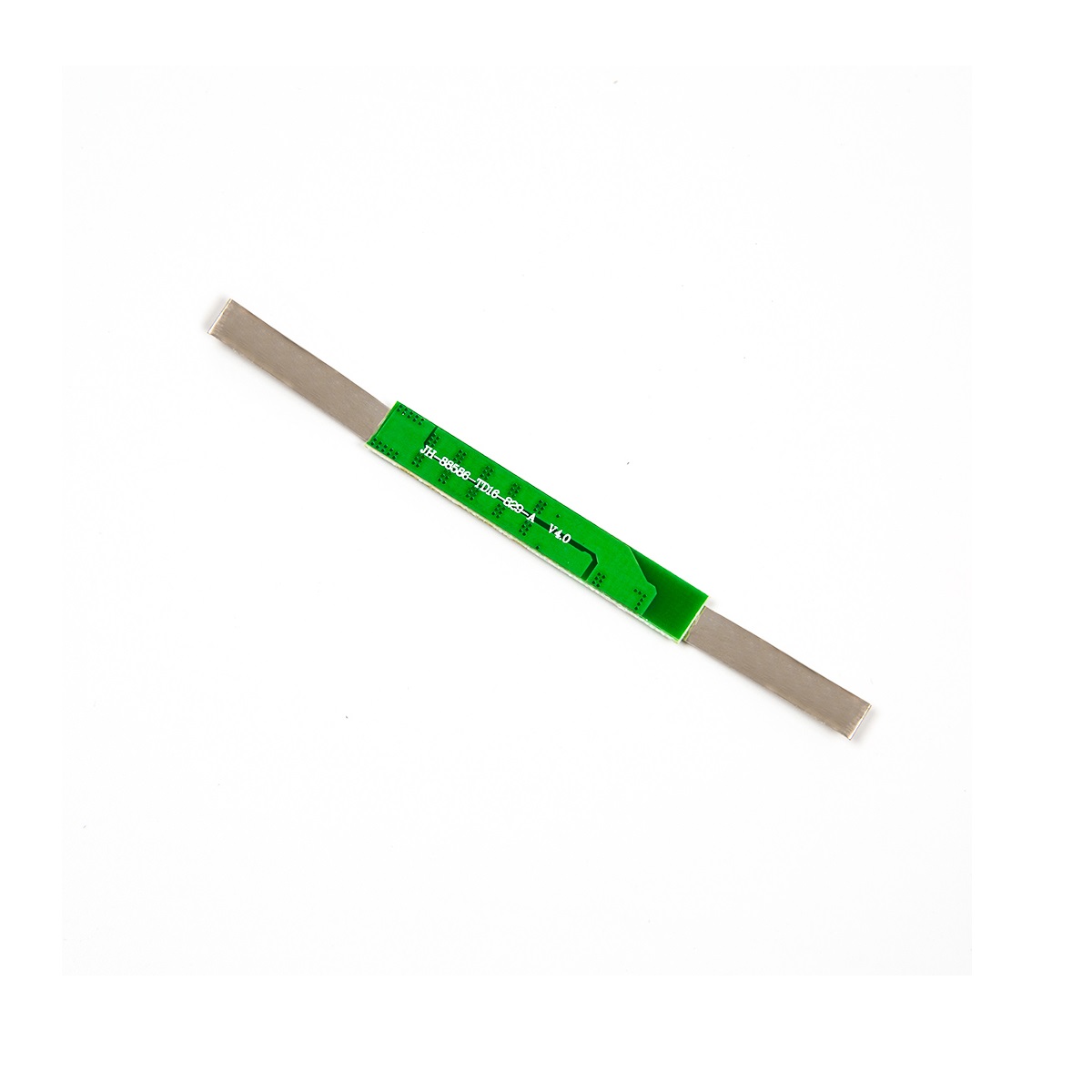
- Compact PCB Format: Designed for integration into compact single-cell battery-powered assemblies.
- Parallel Cell Pack Compatibility: Can be incorporated into a parallel-connected 18650 battery group, provided the pack voltage and current requirements are compatible with the protection board.
Battery Configuration & Voltage Details
This protection board is intended for a 1S lithium-ion battery configuration. In a 1S pack, cells connected in parallel operate as a single voltage group. Connecting additional cells in parallel increases the available battery capacity, but does not increase the nominal pack voltage.
| Battery Parameter | Value |
|---|---|
| Battery Configuration | 1S (single series group) |
| Typical Cell Chemistry | Lithium-ion |
| Nominal Battery Voltage | 3.7V |
| Typical Full-Charge Voltage | 4.2V |
| Parallel Cell Arrangement | Multiple cells connected in parallel as one series group |
Important: This is a battery protection board, not a standalone lithium-ion charger. Use a suitable 1S lithium-ion charging circuit with a regulated 4.2V charging output. The 3.7V value represents the nominal battery voltage, not the full-charge charging voltage.
Protection Functions & Operating Thresholds
The protection circuit is designed to monitor important battery operating conditions. Its specified voltage and current detection parameters are listed below.
| Protection Parameter | Specified Value |
|---|---|
| Overcharge Detection Voltage | 4.25V ± 0.05V |
| Overcharge Release Voltage | 4.23V ± 0.05V |
| Over-Discharge Detection Voltage | 2.45V ± 0.1V |
| Overcurrent Detection Value | 7.5A |
| Listed Ceiling Continuous Current | 12A |
| Short-Circuit Protection | Provided |
Battery & External Circuit Connection Details
The board provides four connection terminals divided into battery-side connections and protected external circuit connections. Correct terminal identification is essential for proper integration.
| Terminal | Connection Description |
|---|---|
| B+ | Connect to the positive terminal of the lithium-ion battery pack. |
| B− | Connect to the negative terminal of the lithium-ion battery pack. |
| P+ | Positive terminal for the protected external circuit connection. |
| P− | Negative terminal for the protected external circuit connection. |
The external load and compatible charging circuit should be connected through the designated protected output terminals. Observe the marked polarity and use appropriately rated wiring for the intended current.
Applications
This 1S lithium-ion battery protection board can be integrated into electronic projects and battery-powered equipment that use a compatible single-cell-group battery pack.
- 18650 Battery Packs: Protection circuit integration for single-series-group 18650 lithium-ion battery assemblies.
- Portable Electronic Projects: Battery protection for compact DIY electronics powered by a 3.7V lithium-ion pack.
- Rechargeable LED Lighting: Suitable for compatible single-cell-group battery-powered LED lighting projects.
- Wireless Sensor Devices: Protection for battery-powered sensor nodes and monitoring electronics.
- IoT Development Projects: Integration into compatible rechargeable battery-powered IoT prototypes.
- Microcontroller-Based Devices: Battery protection for suitable portable development-board projects.
- DIY Power Modules: Integration into custom 1S lithium-ion battery supply assemblies.
- Portable Instrumentation: Protection for compatible handheld measurement and electronic instruments.
- Rechargeable Consumer Electronics: Use in suitable compact electronic products designed around a 1S lithium-ion battery pack.
- Battery-Powered Prototypes: A protection circuit option for experimental and prototype battery-powered equipment.
Package Contents
- 1 × 1S 18650 3.7V Lithium-Ion Battery Protection Board – 5 MOSFET Configuration
Product Specifications
| Parameter | Specification |
|---|---|
| Product Type | Lithium-Ion Battery Protection Board |
| Battery Configuration | 1S (Single Series Group) |
| Compatible Battery Type | 18650 Lithium-Ion Cells |
| Nominal Battery Voltage | 3.7V |
| Typical Full-Charge Voltage | 4.2V |
| MOSFET Configuration | 5 MOSFETs |
| Overcharge Detection Voltage | 4.25V ± 0.05V |
| Overcharge Release Voltage | 4.23V ± 0.05V |
| Over-Discharge Detection Voltage | 2.45V ± 0.1V |
| Listed Ceiling Continuous Current | 12A |
| Overcurrent Detection Value | 7.5A |
| Protection Functions | Overcharge, over-discharge, overcurrent and short-circuit protection |
| Battery Terminals | B+, B− |
| Protected Output Terminals | P+, P− |
| Shipping Weight | 0.005 kg |
| Shipping Dimensions | 8 × 7 × 1 cm |
Connection & Operating Recommendations
- Verify Battery Configuration: Use only with a compatible 1S lithium-ion battery pack. Do not connect a multi-series-cell battery pack to this board.
- Observe Terminal Polarity: Connect battery positive and negative to B+ and B− respectively, and use P+ and P− for the protected external circuit.
- Use a Compatible Charger: Charge the 1S lithium-ion pack using a suitable 4.2V regulated charging circuit.
- Match Current Requirements: Select the load and wiring according to the board’s verified operating-current capability. Do not assume that the listed 12A ceiling rating is available continuously under all conditions.
- Use Suitable Wiring: Select conductors and connectors appropriate for the expected battery current.
- Prevent Reverse Polarity: Check all battery and output connections before energising the circuit.
- Provide Electrical Insulation: Prevent exposed terminals and PCB conductors from contacting metal enclosures or other conductive surfaces.
- Allow Adequate Heat Dissipation: Avoid enclosing the protection board in a way that causes excessive heat accumulation.