
SPIDER Automation | 1S 12A Li-ion Battery Protection Board | 3.7V 4.2V
Product Overview
The SPIDER Automation 1S 12A Li-ion Battery Protection Board is designed to provide electrical protection for single-cell rechargeable lithium-ion battery packs. It integrates voltage-monitoring and overcurrent-detection circuitry with MOSFET-controlled switching to manage battery charging and discharging under normal operating conditions and during electrical fault events.
Its compact PCB layout and dedicated battery and power terminals make it suitable for integration into custom battery packs, portable electronics and embedded power systems. The board is intended for conventional 3.6V/3.7V nominal Li-ion cells with a 4.2V full-charge voltage.
Technical Features & Protection Functions
- Overcharge Protection: Monitors cell voltage and activates protection when the battery reaches the specified overcharge detection level.
- Over-Discharge Protection: Detects excessive battery discharge and helps prevent the cell voltage from falling below the specified threshold.
- Overcurrent Protection: Detects excessive current conditions to help protect the battery and connected electrical circuit.
- Short-Circuit Protection: Provides a protective response when a short circuit occurs at the external power connection.
- Three-Stage Overcurrent Detection: Integrated detection circuitry supports multiple stages of overcurrent and short-circuit monitoring.
- MOSFET-Based Switching: Controls the battery charge and discharge paths through electronic switching.
- Low-Standby-Current Design: Precision monitoring circuitry is designed to minimize power consumption while the battery pack is in standby.
Electrical Configuration & Battery Compatibility
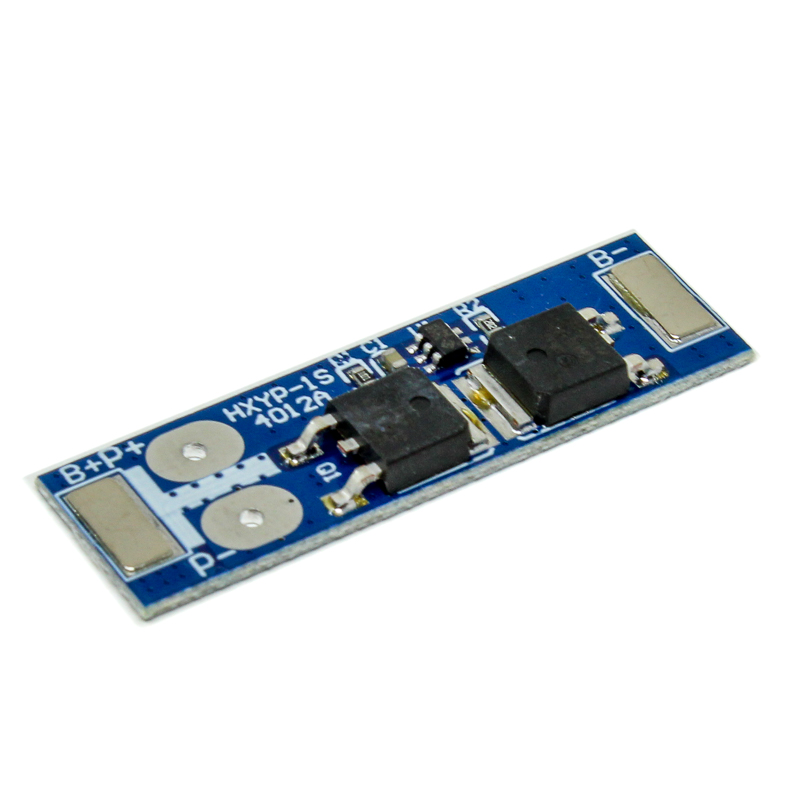
This module is designed for a 1S single-cell Li-ion battery configuration. It connects directly to the positive and negative terminals of one compatible rechargeable lithium-ion cell and provides separate battery-side and external power connections.
A conventional single-cell Li-ion battery has a nominal voltage of 3.6V or 3.7V and a full-charge voltage of 4.2V. Use a dedicated 4.2V CC/CV Li-ion charger. The protection board provides battery protection functions; it does not replace the charging controller.
Connector & Wiring Details
| Terminal | Connection Description |
|---|---|
| B+ | Connect to the positive terminal of the Li-ion battery cell. |
| B− | Connect to the negative terminal of the Li-ion battery cell. |
| P+ | Positive external power and charging connection. |
| P− | Negative external power and charging connection. |
Functional Advantages
- Integrated Protection Architecture: Combines essential voltage and current protection functions on a single PCB.
- Controlled Battery Switching: MOSFET-based control manages the battery connection during normal operation and protection events.
- High-Current Application Support: Provides a 12A continuous current rating for appropriately designed battery-powered circuits.
- Compact System Integration: Its small footprint is suitable for battery-powered designs with limited installation space.
- Simplified Wiring: Clearly identified battery and external power terminals support straightforward electrical integration.
Applications
The 1S 12A protection board can be used in compatible single-cell Li-ion battery assemblies where the battery chemistry, current demand and electrical characteristics match the module’s specifications.
- Custom 18650 Battery Packs: Protection circuitry for compatible single-cell 18650 Li-ion assemblies.
- Portable Electronic Equipment: Battery protection for suitable rechargeable portable devices.
- DIY Power Projects: Integration into custom-built single-cell battery-powered circuits.
- Embedded Electronics: Battery protection for compact electronic control systems.
- IoT Devices: Protection for compatible battery-powered sensor and communication equipment.
- LED Lighting Systems: Battery protection for suitable single-cell Li-ion LED applications.
- Handheld Instruments: Integration into compatible portable measurement and testing equipment.
- Robotics Prototypes: Battery protection for suitable single-cell-powered robotic electronics.
- Wireless Electronics: Protection for compatible battery-powered wireless devices.
- Compact Battery Modules: Integration into custom power assemblies requiring single-cell Li-ion protection.
Package Contents
- 1 × 1S 12A Li-ion Battery Protection Board
Product Specifications
| Parameter | Specification |
|---|---|
| Product Type | Li-ion Battery Protection Board |
| Battery Configuration | 1S (Single Cell) |
| Compatible Battery Chemistry | Conventional rechargeable Li-ion |
| Nominal Battery Voltage | 3.6V / 3.7V |
| Full-Charge Voltage | 4.2V |
| Recommended Charging Voltage | 4.2V CC/CV |
| Upper-Limit Continuous Current | 12A |
| Overcurrent Detection Current | 17A |
| Overcharge Detection Voltage | 4.35V ± 0.25V |
| Overcharge Release Voltage | 4.2V ± 0.25V |
| Over-Discharge Detection Voltage | 2.9V ± 0.05V |
| Protection Functions | Overcharge, over-discharge, overcurrent and short-circuit protection |
| Switching Architecture | MOSFET-controlled charge/discharge switching |
| Overcurrent Detection Circuit | Three-stage detection circuit |
| Battery Terminals | B+, B− |
| External Power Terminals | P+, P− |
| PCB Length | 40mm |
| PCB Width | 12mm |
| PCB Height | 3.5mm |
| Product Weight | Approximately 4g |
Connection & Operating Recommendations
- Correct Battery Configuration: Connect only one compatible conventional Li-ion cell to the B+ and B− terminals.
- Observe Terminal Polarity: Verify battery and external connection polarity before powering the circuit. Reverse connections may damage the board.
- Use a Suitable Charger: Use a dedicated 4.2V CC/CV charger designed for single-cell Li-ion batteries. The protection board is not a standalone charger.
- Continuous Current Management: Keep the actual continuous load within the board’s rated current and consider PCB temperature, conductor size and ventilation.
- Account for Transient Loads: Motors and other inductive or high-startup-current loads can produce brief current surges. Ensure these remain compatible with the protection board’s operating limits.
- Protection Recovery: If the protection circuit disconnects the output following a fault, remove the fault condition before attempting recovery. A suitable charger connection may be required to restore normal operation.
- ESD Precautions: Handle the PCB using appropriate electrostatic-discharge precautions, particularly during installation and wiring.
- Battery Compatibility: Use a cell with a suitable discharge-current rating for the intended application. The board’s current rating does not increase the battery cell’s own current capability.