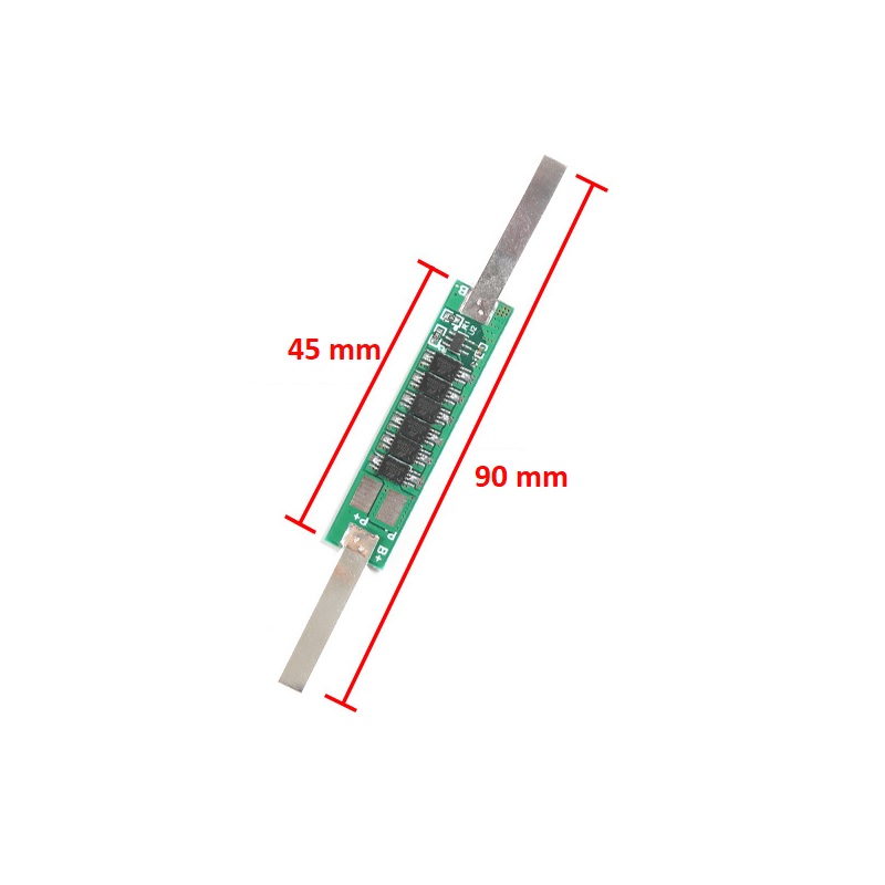

SPIDER Automation | 1S 3.7V 18650 Lithium-Ion Battery Protection Board | 6 MOSFET
The SPIDER Automation 1S Lithium-Ion Battery Protection Board is designed to provide essential electrical protection for single-cell lithium-ion battery packs. It monitors battery voltage and current conditions through its protection circuitry and controls the battery connection when specified abnormal operating conditions are detected.
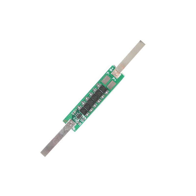
Built around the DW01 protection IC and 8205A MOSFET components, this compact module integrates multiple protection functions into a small PCB. It is suitable for battery assemblies using a single lithium-ion cell or multiple compatible cells connected in parallel, making it useful for custom battery-powered electronics and portable equipment.
Technical Features & Protection Functions
- Overcharge Protection: Monitors cell voltage and interrupts the charging path when the overcharge protection threshold is reached.
- Over-Discharge Protection: Helps prevent excessive battery discharge by disconnecting the protected circuit when the low-voltage threshold is detected.
- Overcurrent Protection: Detects excessive current conditions and controls the battery output path to protect the circuit.
- Short-Circuit Protection: Provides a protective response when a short-circuit condition is detected at the protected output.
- DW01 Protection Controller: Uses a dedicated battery protection IC for voltage monitoring and protection control.
- 6-MOSFET Switching Arrangement: Incorporates MOSFET components for controlling battery charging and discharging paths.
- Compact Circuit Design: Integrates the protection circuitry into a small PCB for space-conscious battery pack construction.
Battery Configuration & Compatibility
This board is intended for a 1S conventional lithium-ion battery configuration. Multiple compatible cells may be connected in parallel to increase the overall battery capacity while retaining the same nominal voltage as a single cell.
- Single-Cell Pack: Suitable for one conventional 3.7V nominal lithium-ion cell.
- Parallel Battery Pack: Compatible with appropriately matched cells connected in parallel.
- Voltage Configuration: Parallel-connected cells retain the voltage of the individual cells; their capacities are combined.
- Cell Compatibility: Use cells with matching chemistry, nominal voltage, capacity and condition when assembling a parallel battery pack.
Battery & Output Connection Details
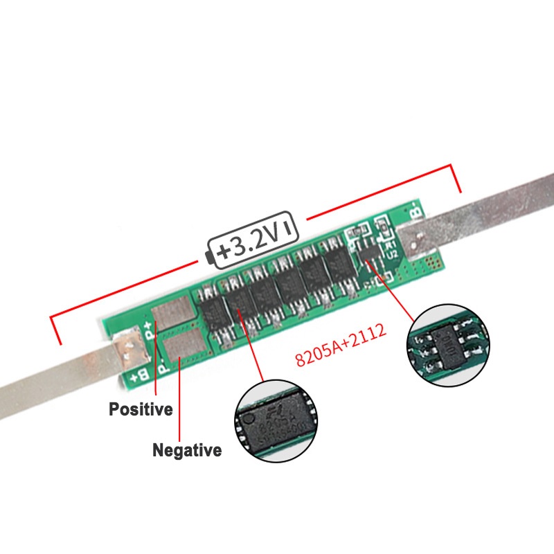
The board provides separate battery-side and protected output terminals. Connect the battery directly to the designated B terminals, and connect the external charger and load through the protected P terminals.
| Terminal | Connection Description |
|---|---|
| B+ | Connect to the positive terminal of the battery or parallel battery pack. |
| B- | Connect to the negative terminal of the battery or parallel battery pack. |
| P+ | Protected positive connection for the external charger and load. |
| P- | Protected negative connection for the external charger and load. |
Connection arrangement: B+ and B- connect to the battery pack, while P+ and P- connect to the external charging and discharging circuit. Follow the PCB terminal markings carefully to maintain correct polarity.
Applications
This protection module can be integrated into compatible single-cell lithium-ion battery assemblies used in a variety of portable and embedded electronic applications.
- 18650 Battery Packs: Protection circuitry for single-cell and parallel-connected 18650 battery assemblies.
- DIY Power Banks: Battery protection in custom power bank projects designed around a 1S battery pack.
- Portable Electronics: Suitable for compatible rechargeable electronic devices.
- Rechargeable LED Lighting: Protection for single-cell battery-powered LED lights and lamps.
- Bluetooth Speakers: Battery protection in compatible portable audio equipment.
- Wireless Devices: Integration into rechargeable wireless electronic products.
- IoT Projects: Battery protection for suitable single-cell wireless sensor and monitoring devices.
- Embedded Electronics: Use in custom battery-powered embedded systems.
- Portable Instruments: Protection for compatible handheld measurement and testing equipment.
- DIY Battery Projects: A protection solution for custom 1S lithium-ion battery assemblies.
Package Contents
- 1 × 1S 3.7V Lithium-Ion Battery Protection Board – 6 MOSFET
Product Specifications
| Parameter | Specification |
|---|---|
| Product Type | Lithium-Ion Battery Protection Board (BMS / PCM) |
| Model | 1S 3.7V 9A 6MOS |
| Battery Configuration | 1S (Single Cell) |
| Compatible Battery | Conventional 3.7V nominal Lithium-Ion / 18650 cells |
| Nominal Battery Voltage | 3.7V |
| Full-Charge Voltage | 4.2V |
| Maximum Continuous Current | 12A |
| Overcurrent Detection Current | 15A |
| Overcharge Detection Voltage | 4.25V ±0.05V |
| Overcharge Release Voltage | 4.23V ±0.05V |
| Over-Discharge Detection Voltage | 2.45V ±0.1V |
| Protection Functions | Overcharge, over-discharge, overcurrent and short-circuit protection |
| Protection IC | DW01 |
| MOSFET Components | 8205A |
| MOSFET Quantity | 6 |
| Battery Terminals | B+, B- |
| Output Terminals | P+, P- |
| PCB Length | 35mm |
| PCB Width | 7.4mm |
| PCB Thickness | 2.2mm |
Connection & Operating Recommendations
- Use the Correct Battery Chemistry: This board is intended for conventional 3.7V nominal lithium-ion cells. Do not use it with LiFePO4 cells or other battery chemistries.
- Connect Cells in Parallel Only: Multiple cells must be connected in parallel to retain the intended single-cell voltage configuration. Do not connect cells in series.
- Match Parallel Cells: Use cells with compatible voltage, capacity, chemistry and condition. Ensure their voltages are properly matched before connecting them in parallel.
- Observe Terminal Polarity: Connect B+ and B- to the battery and P+ and P- to the external circuit according to the PCB markings.
- Use a Suitable Charger: Use a dedicated 1S lithium-ion CC/CV charger with the correct full-charge voltage.
- Respect Current Ratings: Keep continuous operation within the specified current rating. The overcurrent detection threshold is a protection parameter, not an operating-current rating.
- Choose Appropriate Wiring: Use suitable wire gauge, secure solder joints and proper insulation for the intended current.
- Prevent Short Circuits: Insulate exposed terminals and protect the PCB from contact with conductive enclosure surfaces.