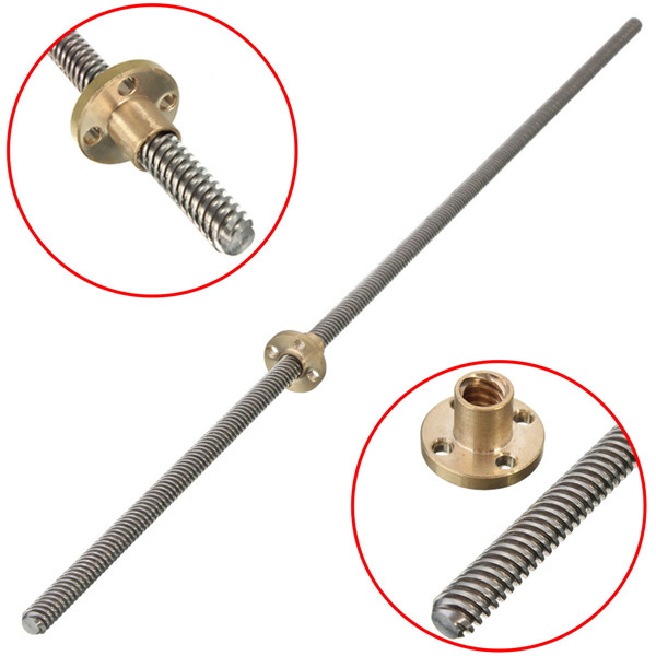

SPIDER Automation | 300mm T8 Trapezoidal Lead Screw with Brass Nut | Single-Start Linear Motion Drive
The T8 Trapezoidal Lead Screw with Brass Nut is designed to convert rotary motion into controlled linear displacement. It is suitable for mechanical positioning systems in which a stepper motor or other rotary drive mechanism moves a component along a linear axis.
The lead screw features a single-start trapezoidal thread with an 8mm nominal diameter and 2mm pitch. Since the screw has one thread start, its lead is also 2mm, meaning the mating nut travels 2mm along the screw for each complete revolution, assuming no slip or backlash-related displacement. The included brass nut provides the threaded engagement required for the linear drive mechanism.
Technical Features & Functional Characteristics
- Trapezoidal Thread Profile: Designed for mechanical power transmission and controlled linear movement.
- Single-Start Thread Design: Provides a lead equal to the thread pitch, making linear travel per revolution straightforward to calculate.
- Rotary-to-Linear Motion Conversion: Converts rotation from a compatible motor or drive mechanism into linear displacement through the mating nut.
- Brass Nut Interface: Includes a brass nut that engages with the lead screw to produce linear movement.
- Stainless Steel Construction: The screw is described as stainless steel, offering mechanical strength and corrosion resistance.
- Stepper Motor Compatibility: Suitable for compatible stepper-driven positioning and linear-motion assemblies.
- Practical Installation: Can be integrated into machine frames and linear guide arrangements using suitable supports and couplings.
Thread Pitch, Lead & Linear Travel
The lead screw uses a single-start thread. Pitch refers to the distance between corresponding points on adjacent thread turns, while lead is the linear distance travelled by the nut during one complete revolution of the screw.
For this single-start configuration, pitch and lead are equal. The nut therefore advances by 2mm per revolution. This relationship can be used when calculating the required motor rotation for a target linear movement.
Applications
The T8 lead screw is suitable for linear positioning and mechanical drive systems that use a compatible trapezoidal screw and nut arrangement.
- FDM 3D Printers: Z-axis movement and other compatible linear positioning mechanisms.
- CNC Machines: Linear drive arrangements for compatible machine axes and positioning assemblies.
- Stepper Motor Linear Actuators: Converts stepper motor rotation into controlled linear displacement.
- Desktop CNC Equipment: Mechanical positioning in compact CNC platforms.
- DIY 3D Printer Projects: Replacement or construction component for compatible T8 lead screw assemblies.
- Automation Equipment: Linear movement mechanisms in compact automated machines.
- Laboratory Positioning Systems: Screw-driven adjustment mechanisms requiring controlled linear travel.
- Mechanical Prototypes: Rotary-to-linear drive systems used in engineering and motion-control development.
Package Contents
- 1 × T8 Trapezoidal Lead Screw
- 1 × Brass Nut
Product Specifications
| Parameter | Specification |
|---|---|
| Product Type | Trapezoidal Lead Screw with Nut |
| Thread Designation | T8 |
| Lead Screw Length | 300mm |
| Thread Diameter | 8mm |
| Number of Starts | 1 (Single Start) |
| Thread Pitch | 2mm |
| Lead per Revolution | 2mm |
| Nut Material | Brass |
| Nut Dimensions (Diameter × Height) | 22 × 13mm |
| Screw Material | Stainless Steel |
Installation & Operating Recommendations
Correct alignment between the lead screw, nut and supporting linear mechanism is important for smooth movement and reduced mechanical wear. Use compatible mounting hardware and a suitable motor coupling when integrating the screw into a positioning assembly.
- Align the Lead Screw: Keep the screw parallel to the intended direction of linear travel to reduce binding and uneven movement.
- Use a Compatible Nut Mount: Secure the brass nut in a suitable mounting bracket while allowing the assembly to travel freely along the screw.
- Select a Suitable Motor Coupling: Use a coupling compatible with the motor shaft and lead screw arrangement.
- Support the Screw Properly: Use suitable end supports to maintain alignment and reduce unwanted vibration during rotation.
- Check Linear Guide Alignment: Ensure the moving assembly and linear guides are aligned with the lead screw before operation.
- Lubricate the Thread: Apply a suitable lubricant to the screw and nut interface to help reduce friction and wear.
- Avoid Excessive Side Loading: The lead screw is intended to transmit axial motion; use linear guides to support side loads and maintain the moving assembly’s path.
- Check Travel Clearance: Ensure the nut and connected mechanism have sufficient clearance throughout the complete movement range.