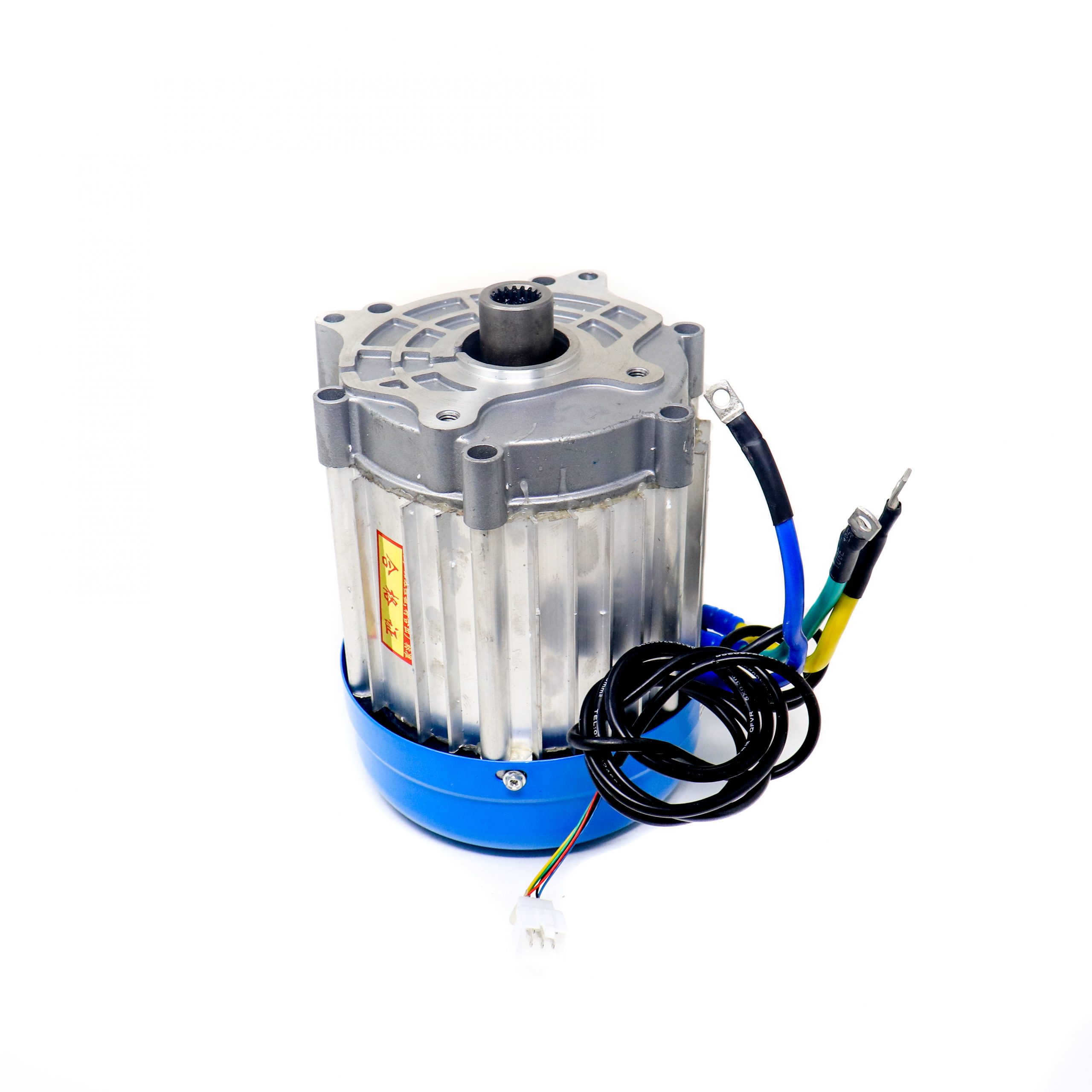

SPIDER Automation | 60V 1500W Brushless DC Motor | Hall-Sensor Electric Drive Motor for E-Bikes & Scooters
Overview
The 60V 1500W Brushless DC (BLDC) Motor is an electric drive motor intended for compatible electric mobility and mechanical drive applications. Its brushless construction requires an electronically commutated BLDC controller for operation. Integrated Hall-effect sensors provide rotor-position information to a compatible controller, supporting motor commutation and speed feedback where the controller provides that functionality.
This motor can be considered for electric scooters, e-bike conversions, robotics and custom drive projects. Correct integration depends on matching the controller, battery supply, mechanical mounting and transmission to the motor’s electrical and mechanical requirements.
Technical Features & Functional Characteristics
- Brushless Motor Technology: Uses electronic commutation through a compatible BLDC controller rather than a conventional mechanical brush-and-commutator arrangement.
- Hall-Effect Rotor Detection: Integrated Hall sensors provide rotor-position signals used by compatible controllers for commutation.
- Speed Feedback Capability: Hall-sensor switching can be used by a compatible controller to derive rotor-speed information.
- Electric Mobility Applications: Suitable for integration into compatible electric scooter and e-bike drive systems.
- Custom Drive Integration: Can be considered for robotics and other mechanical drive projects when electrical and mounting requirements are matched.
Electrical & Motor Performance
The motor is specified for a 60V supply and 1500W rated power, with a rated rotational speed of 3200RPM. It must be operated using a compatible BLDC controller and a suitable power source. Actual vehicle speed and drive performance depend on the controller configuration, battery characteristics, mechanical transmission, wheel size and applied load.
Hall-Sensor Function
Hall-effect sensors detect changes in the magnetic field as the motor rotor turns. Their signals allow a compatible controller to determine rotor position and sequence the motor phase drive correctly. The switching signals may also be used for speed feedback when supported by the controller.
The motor’s Hall-sensor wiring must be connected according to the motor and controller documentation. Wire colours, connector type, pin assignment and sensor supply details are not included in the available product specifications.
Applications
- Electric Scooters: For compatible 60V electric scooter drive systems designed around the motor’s power and speed ratings.
- E-Bike Conversion Projects: For custom electric bicycle builds where the motor mounting and drive arrangement are compatible.
- Electric Mobility Prototypes: For development and testing of electric vehicle drive systems using a suitable BLDC controller.
- Robotics: For robotic platforms requiring a compatible brushless motor drive and mechanical transmission.
- Custom Electric Vehicles: For experimental vehicle projects with appropriately matched electrical and mechanical components.
- Mechanical Drive Systems: For compatible rotating-drive applications requiring electronically controlled BLDC operation.
Package Contents
- 1 × 60V 1500W Brushless DC Motor
Product Specifications
| Parameter | Specification |
|---|---|
| Product Type | Brushless DC Motor (BLDC) |
| Rated Voltage | 60V |
| Rated Power | 1500W |
| Rated Speed | 3200RPM |
| Motor Construction | Brushless DC |
| Rotor Position Detection | Integrated Hall-effect sensors |
| Motor Weight | 9304g (9.304kg) |
| Control Requirement | Compatible BLDC motor controller |
| Package Quantity | 1 motor |
Connection & Operating Recommendations
For reliable integration, use a BLDC controller and power system matched to the motor’s rated electrical requirements. Follow the motor and controller connection documentation for phase and Hall-sensor wiring.
- Controller Matching: Select a BLDC controller compatible with a 60V motor and the motor’s rated power. Confirm its current rating and Hall-sensor support before connection.
- Power Supply: Use a suitable battery system whose voltage range is compatible with the controller and motor. Account for the battery’s fully charged voltage, not only its nominal voltage.
- Phase-Wire Connection: Connect the motor phase wires according to the controller manufacturer’s wiring documentation. Incorrect phase combinations can cause improper operation or excessive current.
- Hall-Sensor Wiring: Follow the documented Hall-sensor supply, ground and signal assignments. Do not determine pin assignments from wire colour alone.
- Mechanical Mounting: Secure the motor using a mounting arrangement designed for its dimensions, torque reaction and operating loads.
- Load & Transmission: Match the coupling, chain, belt or other transmission components to the motor speed and mechanical load.
- Initial Testing: Test the motor at low load and check rotation, controller response, wiring temperature and abnormal vibration before normal operation.
- Electrical Isolation: Disconnect the battery before making or changing motor and controller connections.