
SPIDER Automation | E-Bike Electric Brake Lever Set with Integrated Cut-Off Switch | Left & Right Aluminium Alloy Levers
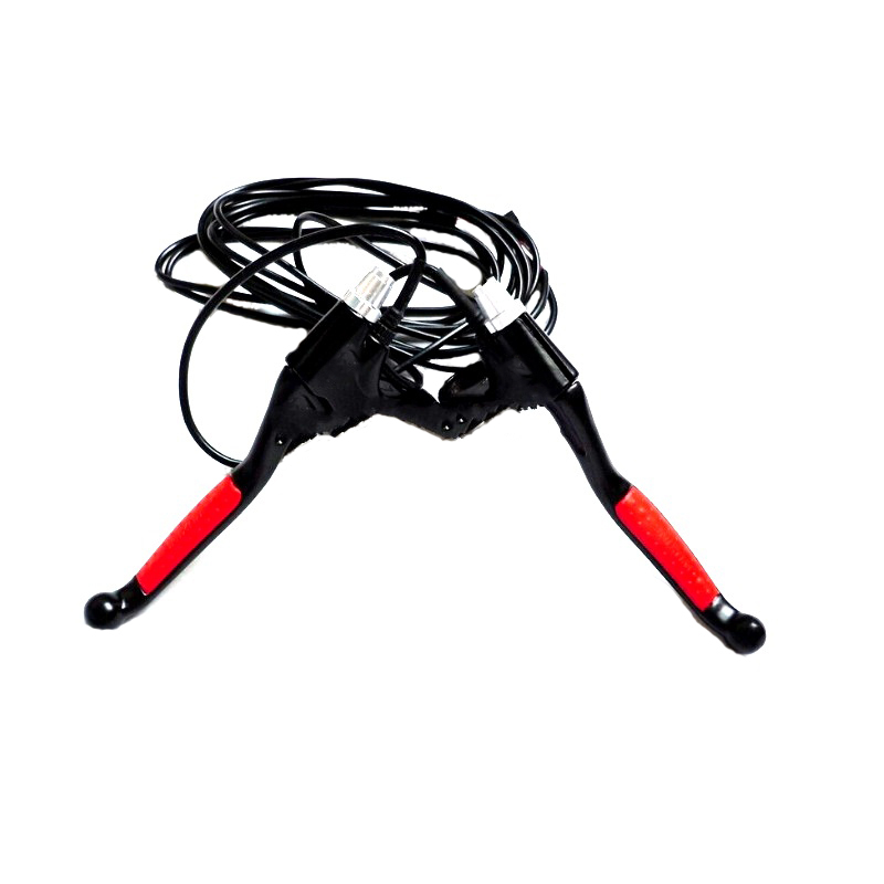
The SPIDER Automation E-Bike Electric Brake Lever Set combines mechanical brake-lever operation with an integrated electrical switch for compatible electric bicycle systems. When a lever is squeezed, its switch provides a brake signal to the motor controller. The controller can then disable motor drive or activate another supported braking function according to its configuration.
The set includes one left and one right brake lever, constructed from aluminium and aluminium alloy. Each lever incorporates an electrical brake-switch function and connects through a low-level signal cable. The specified handlebar mounting dimension is 22.5mm, the listed cable length is 130cm, and the switch workload rating is 0.5A at 60V.
Product Overview & Operating Principle
Electric bicycles commonly use a motor controller to manage motor operation in response to throttle, pedal-assist and brake inputs. An electric brake lever adds an electrical signal to the conventional mechanical braking action. When the rider squeezes the lever, the integrated switch changes its contact state and sends a signal to the controller’s compatible brake input.
The controller uses this signal according to its programmed logic. In a typical motor cut-off arrangement, the controller stops supplying drive command to the motor while the brake input is active. If the controller supports regenerative braking, it may also use the brake signal to request that function. Regenerative braking is dependent on the controller and motor system; it is not generated by the brake lever itself.
Technical Features & Functional Characteristics
- Integrated Brake-Signal Switch: Each lever incorporates an electrical switch that changes state when the brake is applied, providing a signal for compatible controller inputs.
- Controller-Based Motor Cut-Off: Supports interruption of motor drive through the controller’s brake-input logic when the rider applies the mechanical brake.
- Left and Right Lever Design: Supplied as a matched pair for installation on both sides of a compatible handlebar.
- Aluminium Alloy Lever Construction: Uses aluminium and aluminium alloy materials for the mechanical lever assembly.
- Low-Level Electrical Connection: The brake switch is intended to provide a control signal rather than carry the main motor current.
- Non-Polarised Switch Wiring: The supplier identifies no positive or negative polarity distinction for the two-wire brake switch cable.
- 130cm Cable Length: Provides cable reach for routing the brake signal from the handlebar area to a compatible controller connection.
- 22.5mm Handlebar Specification: Intended for compatible bicycle handlebar mounting arrangements matching the listed dimension.
- Mechanical Brake Integration: Provides a lever-operated mechanical braking interface together with an electrical brake signal for the controller.
Integrated Brake Cut-Off Switch
The integrated switch provides an electrical indication of brake operation. When the lever is squeezed, the switch changes state and communicates the braking condition to the motor controller through the brake signal wiring.
This function is particularly useful in throttle-controlled electric bicycles, where the controller can use the brake signal to override the motor-drive request. It helps coordinate motor operation with the rider’s braking action and reduces the possibility of continued powered drive while the brake is applied.
The switch is rated for a workload of 0.5A at 60V. This is the switch’s electrical workload rating, not a motor-current rating. It should be connected to a compatible controller signal circuit rather than used as a direct high-current motor or battery disconnect.
Brake Cable & Electrical Connection
The brake lever uses a low-level electrical switch cable for connection to a compatible electric brake input. The supplier specifies that the two switch wires have no positive or negative polarity distinction, so either wire can be connected to either terminal of a compatible non-polarised brake-switch input.
- Connection Type: Two-wire brake-switch signal connection.
- Polarity: No positive or negative polarity distinction for the switch cable.
- Cable Length: 130cm as listed in the specification table.
- Switch Workload: 0.5A at 60V.
- Intended Interface: Compatible electric motor controller brake input.
Check the controller’s brake-input requirements before installation. The switch’s non-polarised wiring does not mean it is compatible with every controller input or wiring arrangement.
Mechanical Construction & Handlebar Installation
The lever assembly uses aluminium and aluminium alloy construction and is supplied as a left-and-right pair. The listed handlebar mounting specification is 22.5mm, making it important to check the handlebar diameter and lever-clamp fit before installation.
The lever provides the rider’s mechanical braking input while the integrated switch communicates brake operation to the electric control system. Compatibility with the existing mechanical or hydraulic brake arrangement depends on the lever’s mechanical interface and the bicycle’s brake configuration. Confirm the physical fit and brake-system compatibility before replacing existing levers.
Applications
This electric brake lever set is intended for compatible bicycle and electric mobility configurations that use a handlebar brake lever with an electronic brake signal input.
- Electric Bicycles: Brake-signal integration for e-bikes using a controller with a compatible electric brake input.
- Mountain E-Bikes: Replacement or upgrade of compatible handlebar brake levers in electric mountain bicycle configurations.
- Road E-Bikes: Electronic brake cut-off integration for compatible road-style electric bicycles.
- Throttle-Controlled E-Bikes: Provides a brake signal that allows the controller to override motor-drive input during braking.
- Electric Bicycle Conversions: Adds an electrical brake-switch function to a suitable compatible conversion setup.
- E-Bike Brake Lever Replacement: Replaces compatible worn or damaged lever assemblies that require an integrated electrical switch.
- Controller-Based Regenerative Braking Systems: Can provide the brake input used by controllers that support regenerative braking functionality.
- Electric Bicycle Maintenance: Suitable for servicing and replacing compatible electric brake lever assemblies.
Package Includes
- 1 × Left Electric Brake Lever with Integrated Switch
- 1 × Right Electric Brake Lever with Integrated Switch
Product Specifications
| Parameter | Specification |
|---|---|
| Brand | SPIDER Automation |
| Product Type | Electric Bicycle Brake Lever with Integrated Switch |
| Product Category | E-Bike Brake Control Component |
| Package Configuration | Left and Right Lever Pair |
| Mechanical Lever Material | Aluminium and Aluminium Alloy |
| Handlebar Mounting Specification | 22.5mm |
| Integrated Electrical Function | Brake-Signal Switching / Controller Motor Cut-Off Input |
| Switch Workload Rating | 0.5A at 60V |
| Brake Switch Cable Type | Two-Wire Low-Level Signal Cable |
| Cable Polarity | Non-Polarised; No Positive or Negative Wire Distinction |
| Cable Length | 130cm (as listed in the specification table) |
| Brake Function | Mechanical Lever Operation with Electrical Brake Signal |
| Product Weight | 245g per supplied pair |
| Package Quantity | 2 Pieces (Left and Right) |
Installation & Operating Recommendations
Correct mechanical fitment and electrical integration are both important when installing electric brake levers. The levers must operate the bicycle’s braking system correctly while their integrated switches provide the intended signal to the motor controller.
- Confirm Handlebar Fitment: Check compatibility with the specified 22.5mm mounting dimension and ensure that the lever clamps securely to the handlebar.
- Check Brake-System Compatibility: Confirm that the lever’s mechanical arrangement is suitable for the bicycle’s existing brake system before installation.
- Connect to the Brake Input: Wire the integrated switch to the controller’s designated electric brake input, following the controller’s wiring documentation.
- Observe the Switch Rating: Keep the connected electrical load within the 0.5A at 60V switch workload rating. Do not use the switch as a direct motor-current disconnect.
- Route the Cable Carefully: Secure the 130cm signal cable away from moving parts, sharp edges and areas where steering or suspension movement could pull or damage it.
- Check Lever Movement: Ensure that both levers move freely, return correctly and do not interfere with the handlebar grip or other controls.
- Test the Brake Signal: With the drive system safely disabled or the vehicle securely supported, check that squeezing each lever activates the controller’s intended brake response.
- Verify Mechanical Braking: Check the actual braking action independently of the electrical switch before riding the vehicle.