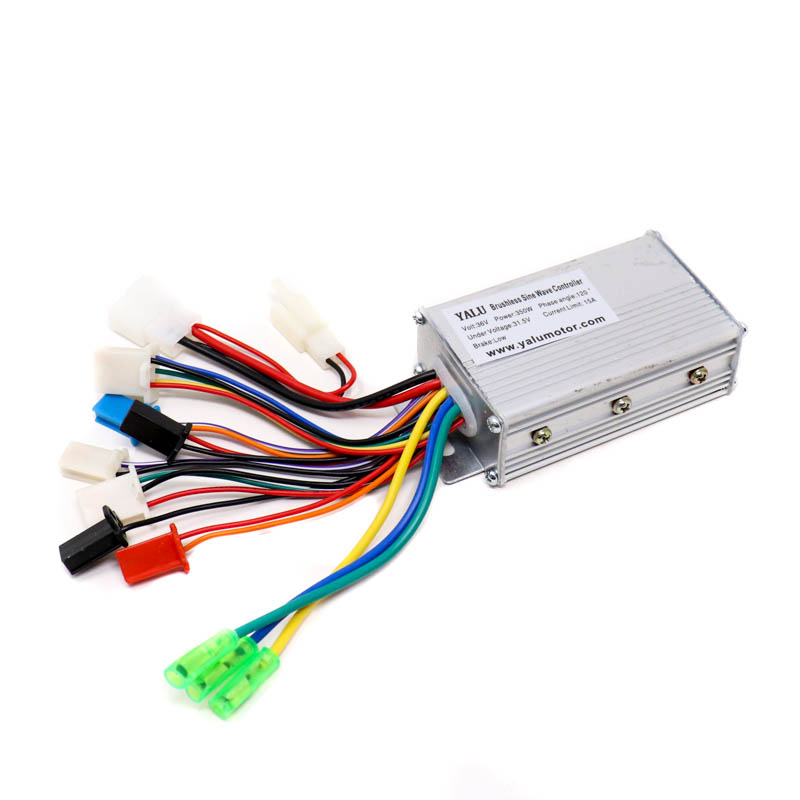
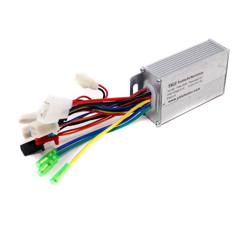

SPIDER Automation | 36V 350W Brushless Sine Wave E-Bike Hub Motor Controller | 31–36V, 15A Current Limit
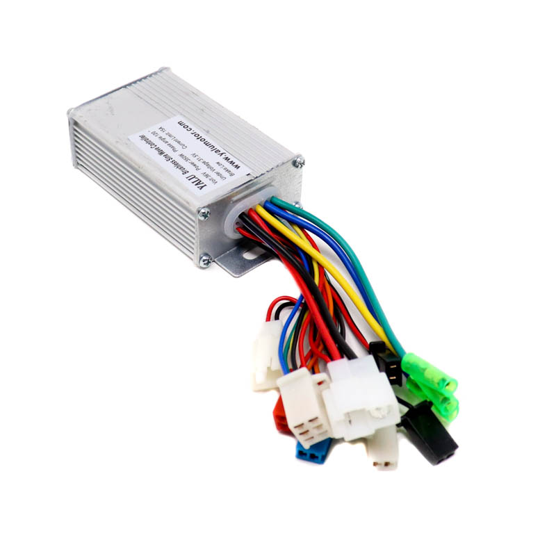
The SPIDER Automation 36V 350W Brushless Sine Wave Motor Controller is an electronic control unit designed for compatible brushless hub motors used in electric bicycles and electric mobility systems. It manages the electrical drive supplied to the motor and provides connection interfaces for the battery, accelerator, brake system and other supporting electrical components.
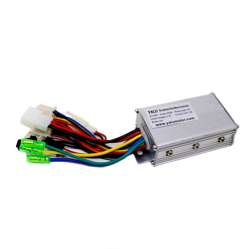
The controller operates within a specified voltage range of 31–36V, with a rated power of 350W and a listed current limit of 15A. In addition to the motor and battery connections, it includes provisions for battery charging, brake-light integration and power-lock control. Its sine-wave controller design is intended for compatible brushless motor configurations. Correct operation requires matching the motor’s electrical characteristics and wiring arrangement with the controller’s connection configuration.
Product Overview & Motor Control Function
A brushless DC motor controller regulates the electrical power and switching sequence supplied to a brushless motor. It interprets the rider’s accelerator input and manages motor operation according to the controller’s internal drive logic and the connected motor’s electrical configuration.
This controller is intended for 350W brushless hub motor applications and uses a sine-wave control design. It serves as the central electrical interface between the battery, motor and vehicle control components, allowing the motor drive system to operate as part of an integrated electric bicycle installation.
Technical Features & Functional Characteristics
- Brushless Hub Motor Drive: Designed for compatible brushless hub motors rather than brushed DC motors.
- Sine Wave Motor Control: Uses a sine-wave controller architecture for compatible brushless motor operation.
- 350W Motor Application: Rated for use with compatible 350W brushless hub motor systems.
- 31–36V Operating Range: Supports the specified electrical supply range for compatible 36V-class battery systems.
- 15A Current Limit: Provides a listed current limit that must be considered when selecting the motor, battery and associated wiring.
- Accelerator Connection: Provides an interface for a compatible accelerator or throttle to deliver rider speed-demand input.
- Brake Control Connection: Includes a brake interface for integrating compatible brake-control signals into the motor-control system.
- Battery Connection: Provides the electrical connection point for the controller’s battery supply.
- Charging Connection: Includes a designated charging connection provision for integration with a compatible charging arrangement.
- Brake-Light Connection: Provides an interface for connecting a compatible brake-light circuit.
- Power-Lock Interface: Supports connection to a compatible power-lock or ignition-switching arrangement.
- Compact Controller Housing: The 90 × 50 × 30mm enclosure supports integration into compact electric bicycle assemblies.
Sine Wave Brushless Motor Control
The sine-wave design identifies the controller’s motor-drive approach for compatible brushless motors. The controller electronically manages the motor drive according to its internal switching strategy and the feedback or sensing arrangement supported by the connected motor.
For correct operation, the controller must match the hub motor’s phase wiring and, where applicable, its Hall-sensor arrangement. A motor and controller should not be considered compatible based only on matching voltage and wattage ratings.
Connection Interfaces & Electrical Integration
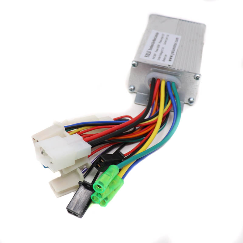
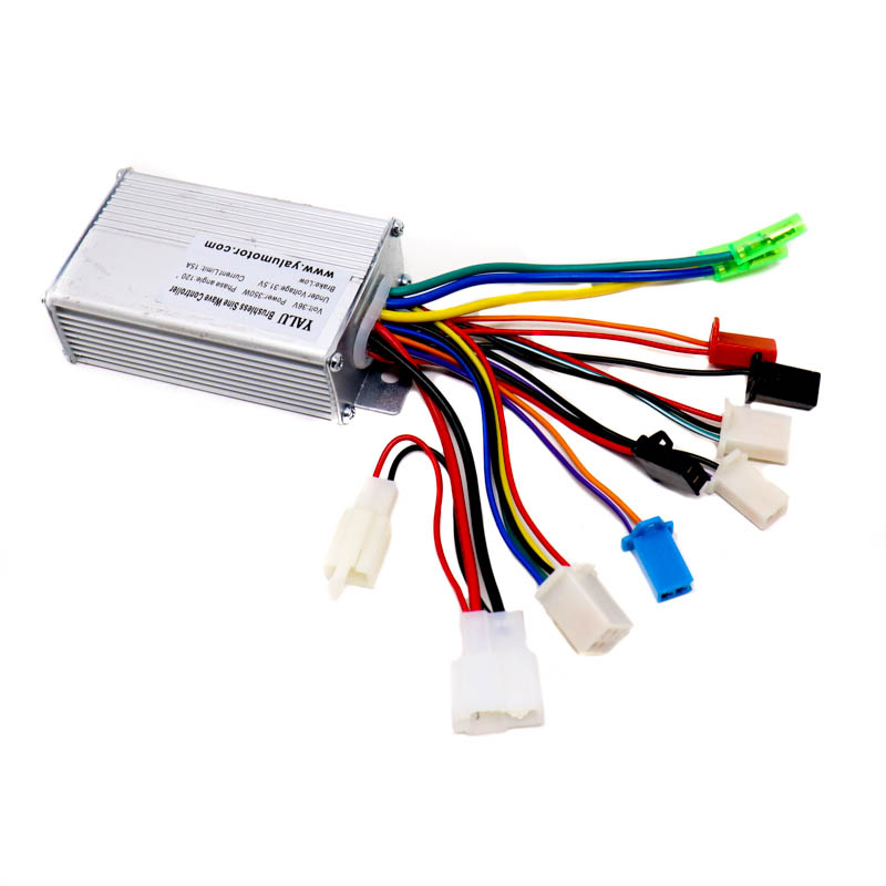
The controller provides connection provisions for the main motor-control system and supporting vehicle components. The identified connection groups include:
| Connection Group | Purpose |
|---|---|
| Motor | Connection to a compatible brushless hub motor. |
| Accelerator | Receives the rider’s throttle or accelerator command. |
| Brake | Provides an interface for a compatible brake-control signal. |
| Battery | Connects the controller to the compatible battery supply. |
| Battery Charging | Provides a designated connection provision for the charging circuit. |
| Brake Light | Supports integration with a compatible brake-light circuit. |
| Power Lock | Provides an interface for a compatible power-lock or ignition-switching circuit. |
The connection groups above describe the functions identified for this controller. Exact wire colours, connector types, pin assignments and terminal polarity must be determined from the actual controller wiring diagram or markings. Do not connect wires based only on appearance or assumptions about common e-bike controller wiring.
Applications
This controller is intended for electric mobility installations using compatible 350W brushless hub motors and an electrical system within its specified operating voltage range.
- Electric Bicycle Hub Motors: Motor control for compatible 350W brushless hub motor e-bikes.
- 36V-Class E-Bike Systems: Integration into compatible battery and motor configurations operating within the 31–36V controller range.
- Electric Scooter Projects: Suitable for compatible scooter configurations using a 350W brushless hub motor and matching control interface.
- E-Bike Conversion Builds: Controller replacement or integration in conversion projects where the motor wiring and electrical ratings match.
- Brushless Hub Motor Replacement: Replacement of an existing controller when its motor-drive and connection configuration is compatible.
- Electric Mobility Prototypes: Motor-control integration for development projects using compatible brushless hub motor systems.
Package Includes
- 1 × 36V Brushless Sine Wave E-Bike Motor Controller for 350W Hub Motor
Product Specifications
| Parameter | Specification |
|---|---|
| Product Type | Brushless DC Motor Controller |
| Controller Design | Sine Wave |
| Motor Application | Brushless Hub Motor |
| Rated Motor Power | 350W |
| Rated Voltage | 31–36V |
| Current Limit | 15A |
| Motor Connection | Brushless Hub Motor Interface |
| Accelerator Connection | Supported |
| Brake Connection | Supported |
| Battery Connection | Supported |
| Charging Connection | Supported |
| Brake-Light Connection | Supported |
| Power-Lock Connection | Supported |
| Length | 90mm |
| Width | 50mm |
| Height | 30mm |
| Product Weight | 211g |
| Package Quantity | 1 Controller |
Connection & Operating Recommendations
Before installing the controller, confirm that the battery, motor and control accessories match its voltage range, current limit and connection requirements. Correct wiring is essential because brushless controllers use specific motor and control interfaces. Follow these recommendations during integration:
- Match the Battery Voltage: Use a compatible battery system that remains within the controller’s specified 31–36V operating range.
- Check Motor Power and Type: Use a compatible 350W brushless hub motor. This controller is not intended for brushed DC motors.
- Verify Motor Wiring: Match the motor’s phase and Hall-sensor connections, where applicable, with the controller’s actual wiring configuration.
- Identify Each Connector: Use the controller’s wiring diagram or terminal markings to identify motor, battery, accelerator, brake, charging, brake-light and power-lock connections.
- Match the Accelerator: Confirm that the throttle’s supply and signal requirements are compatible with the controller before connecting it.
- Check Brake-Signal Compatibility: Ensure that the brake input matches the type of brake switch or sensor used in the vehicle.
- Use Suitable Wiring: Select battery and motor wiring appropriate for the operating current, and secure all electrical connections against loosening and abrasion.
- Mount Securely: Fix the controller in a stable location with suitable protection from water exposure, vibration and mechanical impact.
- Test Before Riding: Verify motor response, accelerator operation, brake cut-off behaviour and power-lock function under controlled conditions before normal vehicle use.