


SPIDER Automation NEO-8M GPS Satellite Positioning Module | M8L-03A-12, NMEA Output & Dual Antenna Support
Description
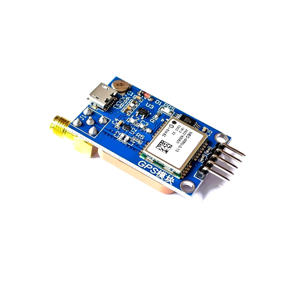
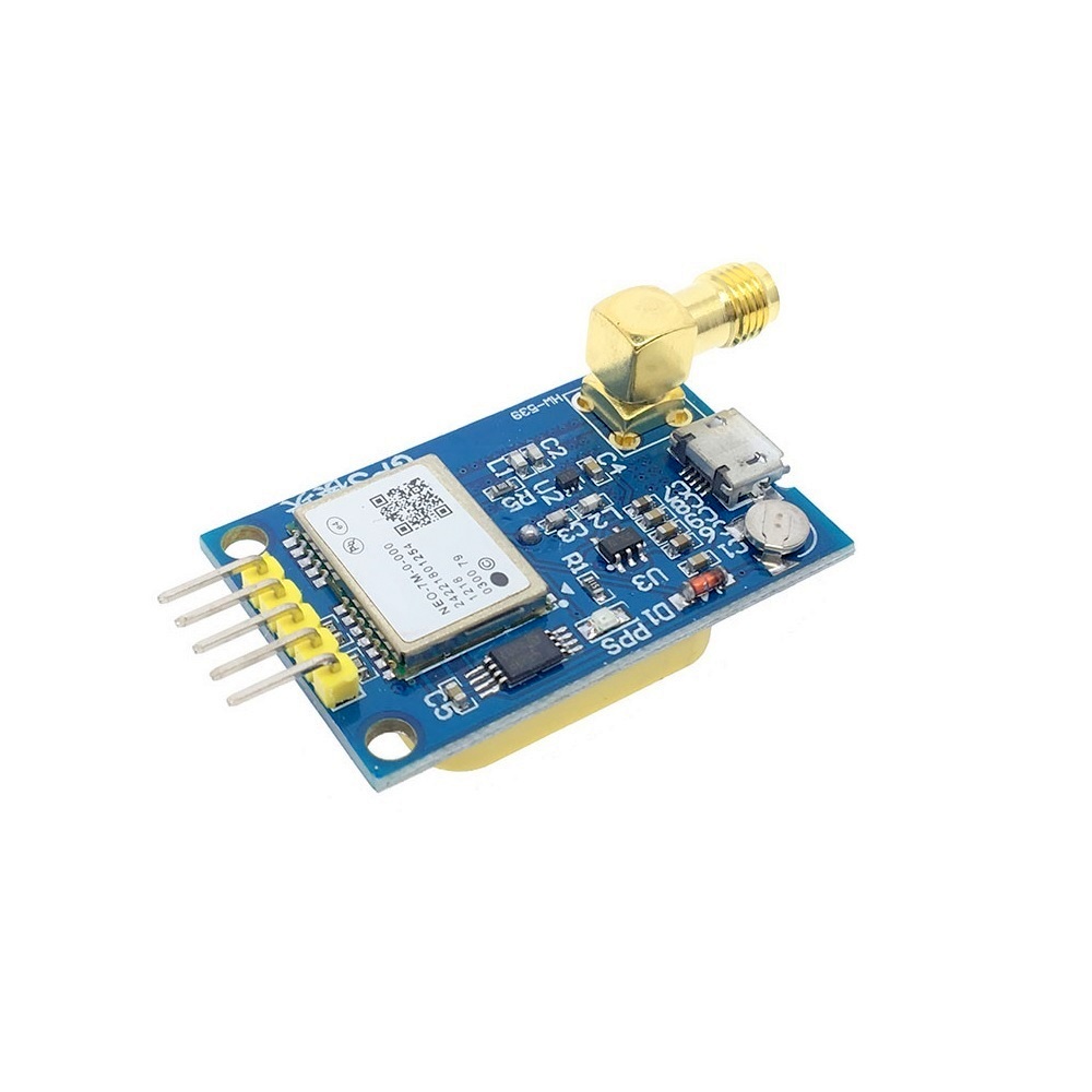
The SPIDER Automation NEO-8M GPS Satellite Positioning Module Development Board (M8L-03A-12) is designed to provide satellite positioning information to embedded navigation, tracking and location-aware electronic systems. Based on the NEO-8M platform, the board supports NMEA standard protocol output and provides serial communication connections for transferring GPS information to an external microcontroller, development board or compatible host system.
The module features an onboard ceramic antenna for satellite reception in suitable open-sky environments, along with an SMA connector for an optional external antenna. This dual antenna arrangement provides flexibility when selecting the antenna configuration according to installation requirements. The onboard Micro USB interface supports debugging and configuration, while the reserved TTL-level UART pins provide a direct serial communication interface for embedded system integration.
A built-in Flash memory stores configuration settings so that saved information can be retained after power-off without an external EEPROM. The board also includes a GPS signal indicator and a dedicated PPX output connection for clock-related pulse signalling.
Technical Features & Performance Characteristics
- NEO-8M-Based Positioning: Uses the NEO-8M GPS platform to provide satellite positioning information for compatible electronic systems.
- Standard NMEA Data Output: Supports NMEA protocol output, enabling GPS information to be processed by compatible navigation software and embedded controllers.
- Integrated Ceramic Antenna: Provides an onboard antenna option for installations with suitable satellite visibility.
- External Antenna Provision: The onboard SMA connector provides an alternative antenna connection for installations requiring a separate GPS antenna.
- Retained Configuration Settings: Built-in Flash memory saves configuration information across power cycles without requiring an external EEPROM for this function.
- Micro USB Debugging: Provides a USB connection for module debugging and configuration through a suitable data cable.
- Dedicated UART Communication: Reserved TXD and RXD connections allow GPS data exchange with external microcontrollers and serial interface adapters.
- GPS Reception Indicator: The onboard signal indicator provides a visual indication of GPS information reception.
- PPX Signal Output: A separate PPX connection is provided for clock-related pulse output applications.
- Flexible Supply Input: The module supports a 3.3–5V DC power supply range.
Electrical Configuration & Interface Details
The development board provides power, ground, serial communication and pulse-output connections. The reserved UART interface operates at TTL logic levels and is intended for direct connection to compatible microcontroller UART pins or suitable USB-to-serial interface modules.
- VCC: Connect to a compatible 3.3–5V DC power source.
- GND: Connect to the ground reference of the power supply and host controller.
- TXD: GPS module serial data output. Connect TXD to the host controller’s RXD input.
- RXD: GPS module serial data input. Connect RXD to the host controller’s TXD output.
- PPX: Dedicated clock-related pulse output connection.
- Micro USB: Used for debugging and configuration through a suitable USB data cable.
- SMA: External antenna connection provided on the development board.
Important interface distinction: The TXD and RXD connections are TTL-level serial interfaces, not RS232 voltage-level interfaces. Do not connect these pins directly to a conventional RS232 port. Use an appropriate level-conversion interface where RS232 communication is required.
Antenna Configuration & Installation
The onboard ceramic antenna provides a convenient reception option for installations where the module can be positioned with suitable visibility of the sky. For installations where the board must be mounted inside an enclosure or away from an appropriate reception location, the SMA connector provides an alternative external antenna connection.
- Onboard Antenna Operation: Use the integrated ceramic antenna in suitable open-sky environments.
- External Antenna Configuration: Use a compatible external GPS antenna through the SMA connection when the installation requires a separate antenna.
- Reception Positioning: Position the antenna with consideration for sky visibility and surrounding obstructions.
- System Integration: Route the UART output to the host controller for processing GPS information.
Applications
The NEO-8M development board can be integrated into electronic systems that require GPS positioning information, NMEA data communication or location-aware functionality. Its USB debugging interface, UART connections and antenna options support a range of embedded engineering and navigation applications.
- GPS Navigation Systems: Provides satellite positioning data for embedded navigation equipment.
- UAV Navigation Integration: Supplies GPS information to compatible flight-control and navigation systems.
- Vehicle Tracking Equipment: Supports location-data acquisition in GPS-based vehicle tracking systems.
- Fleet Monitoring Systems: Provides positioning information for compatible fleet management and tracking equipment.
- Mobile Robotics: Supports GPS-based location awareness in outdoor mobile robotic platforms.
- Autonomous Vehicle Prototypes: Provides positioning data as an input to compatible autonomous navigation architectures.
- Geolocation Data Logging: Supplies GPS information to embedded data loggers and location-recording devices.
- Remote Monitoring Equipment: Enables location information to be incorporated into remote monitoring systems.
- Marine Navigation Electronics: Supports GPS data acquisition in compatible marine navigation equipment.
- Surveying Instrument Integration: Provides positioning information for electronic surveying and field-data acquisition systems.
- Embedded IoT Devices: Adds GPS positioning capability to location-aware IoT hardware.
- GPS-Based Timing Systems: Provides a PPX pulse-output connection for compatible timing and synchronisation designs.
- Microcontroller Development: Supports GPS data acquisition through UART interfaces in embedded controller designs.
- Navigation Data Processing: Provides NMEA-format output for compatible GPS data processing applications.
- Engineering Development Platforms: Supports prototyping and evaluation of GPS-enabled electronic systems.
Package Includes
- 1 × GPS NEO-8M Satellite Positioning Module Development Board (M8L-03A-12)
Product Specifications
| Parameter | Specification |
|---|---|
| Product Type | GPS Satellite Positioning Module Development Board |
| GPS Platform | NEO-8M |
| Model | M8L-03A-12 |
| Primary Function | Satellite positioning and GPS information output |
| Power Supply Voltage | 3.3–5V DC |
| Onboard Antenna | Ceramic GPS antenna |
| External Antenna Connection | SMA connector |
| GPS Data Protocol | NMEA standard protocol output |
| Serial Interface | Reserved TXD and RXD connections |
| Serial Signal Level | TTL level |
| Serial Transmit Pin | TXD – GPS module data output |
| Serial Receive Pin | RXD – GPS module data input |
| USB Interface | Micro USB |
| USB Interface Function | Module debugging and configuration |
| Configuration Memory | Built-in Flash memory |
| Configuration Retention | Saved settings retained after power-off |
| External EEPROM Requirement | Not required for the stated configuration-retention function |
| Signal Indicator | Onboard GPS information reception indicator |
| Pulse Output | PPX |
| Power Connection | VCC and GND |
| UART Connection | TXD to host RXD; RXD to host TXD |
| Direct RS232 Compatibility | Not directly compatible; TTL-to-RS232 level conversion is required |
| Package Quantity | 1 development board |
Connection & Operating Recommendations
- Verify Supply Voltage: Operate the module within its stated 3.3–5V DC supply range and observe the correct VCC and GND connections.
- Cross-Connect UART Signals: Connect module TXD to the host RXD pin and module RXD to the host TXD pin.
- Use Compatible Logic Levels: Confirm that the host controller’s UART signal levels are compatible with the module before connecting the serial interface.
- Avoid Direct RS232 Connection: Use a suitable TTL-to-RS232 converter when interfacing with conventional RS232 equipment.
- Provide Suitable Antenna Visibility: For onboard ceramic antenna operation, position the module where the antenna has suitable visibility of the sky.
- Check External Antenna Compatibility: Confirm connector compatibility and antenna electrical requirements before attaching an external GPS antenna to the SMA connection.
- Allow for Satellite Acquisition: GPS reception and positioning depend on satellite visibility, installation conditions and surrounding obstructions.
- Use a USB Data Cable: Connect the Micro USB interface to a compatible data connection when debugging or configuring the module.
- Retain Configuration Settings: Use the built-in Flash configuration-retention capability when saving supported module settings for subsequent power cycles.
- Verify PPX Requirements: Check the receiving system’s electrical and timing requirements before using the PPX output in a synchronisation circuit.