
SPIDER Automation 28dB Active Ceramic GPS Antenna | 1575.42MHz L1, RHCP & U.FL Interface
Description
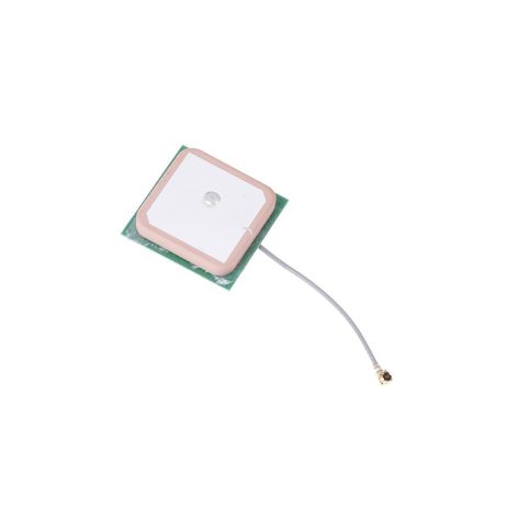
The SPIDER Automation 28dB Active Ceramic GPS Antenna is a compact L1-band antenna assembly designed for GPS satellite signal reception in embedded positioning, navigation and timing equipment. It uses a ceramic patch antenna with integrated active amplification circuitry to receive satellite signals and provide an amplified RF output to a compatible GPS receiver.
Operating at 1575.42MHz ± 4MHz, the antenna uses right-hand circular polarization (RHCP), which is commonly used for GPS L1 reception. Its U.FL connector and approximately 5cm cable support direct connection to compatible GPS receiver boards, including suitable NEO-6M, NEO-7M and NEO-8M module configurations.
The compact ceramic antenna construction supports integration into space-constrained electronic equipment. With a stated gain of 28dB, a typical noise figure of 1.5dB and a VSWR of 1.5, it is intended for GPS positioning, marine navigation and timing-related applications. The antenna requires a compatible power supply for its active amplification circuitry.
Key Features
- GPS L1-Band Reception: Designed for GPS signal reception at 1575.42MHz ± 4MHz.
- Active Ceramic Antenna: Combines a ceramic patch element with integrated signal amplification circuitry.
- 28dB Stated Antenna Gain: Provides an amplified output for compatible GPS receiver systems.
- Right-Hand Circular Polarization: RHCP configuration is suited to GPS satellite signal reception.
- U.FL RF Connector: Provides a compact coaxial interface for compatible receiver boards.
- Short Antenna Cable: Approximately 5cm cable length supports compact board-level installation.
- Compact Ceramic Construction: Supports integration into small GPS navigation and positioning equipment.
- 1.5dB Noise Figure: Provides a stated low-noise characteristic for the active antenna assembly.
- 1.5 VSWR: Provides a stated voltage standing wave ratio for the antenna.
- Wide Operating Temperature Range: Specified for operation from -45°C to +85°C.
Technical Features & Performance Characteristics
- Operating Frequency: The antenna is designed for the GPS L1 frequency centred at 1575.42MHz, with a stated ±4MHz frequency range.
- Active Signal Amplification: The integrated active circuitry amplifies the received RF signal before it is delivered to the GPS receiver.
- RHCP Polarization: Right-hand circular polarization supports compatibility with GPS L1 satellite signal polarization.
- Noise Figure: The stated noise figure is 1.5dB.
- Voltage Standing Wave Ratio: The stated VSWR is 1.5.
- Interference Suppression: A 30dB ± 100MHz interference-suppression figure is provided, but its measurement definition and test conditions require confirmation; it is therefore not used as a performance claim in this description.
Mechanical Design & Installation
- Ceramic Patch Element: The ceramic antenna structure provides a compact form factor for integration into GPS receiver assemblies.
- U.FL Connection: The compact RF connector is suitable for compatible board-level antenna connections.
- Short Cable Assembly: The approximately 5cm cable supports installation near the GPS receiver board.
- Compact Module Format: The antenna is suitable for equipment where available installation space is limited.
Applications
- NEO-6M GPS Receiver Boards: External L1 antenna connection for compatible NEO-6M modules with U.FL antenna input and active antenna power support.
- NEO-7M GPS Modules: GPS L1 signal reception for compatible NEO-7M receiver configurations.
- NEO-8M GPS Modules: External antenna integration with compatible NEO-8M receiver boards.
- Marine Navigation Electronics: GPS signal reception for compatible marine positioning and navigation equipment.
- GPS Timing Systems: Satellite signal reception for GPS-based timing equipment.
- Embedded GPS Devices: Antenna integration in compact embedded positioning systems.
- GPS Development Boards: External antenna connection for compatible GPS development and evaluation platforms.
- Robotics Navigation: GPS reception in outdoor mobile robotics systems using compatible receiver hardware.
- Vehicle Positioning Systems: Antenna integration in GPS-based vehicle tracking and positioning equipment.
- UAV Navigation Electronics: GPS L1 antenna integration in compatible unmanned aircraft navigation systems.
- Remote Monitoring Equipment: GPS positioning support for compatible outdoor monitoring devices.
- Location and Tracking Terminals: External GPS antenna connection for embedded tracking equipment.
Package Includes
- 1 × Active Ceramic GPS Antenna with U.FL Connector and Cable
Product Specifications
| Parameter | Specification |
|---|---|
| Product Type | Active Ceramic GPS Antenna |
| Satellite Navigation System | GPS |
| Operating Frequency | 1575.42MHz ± 4MHz |
| Frequency Band | GPS L1 |
| Antenna Construction | Ceramic Patch with Integrated Active Amplifier |
| Stated Antenna Gain | 28dB (gain reference requires confirmation) |
| Polarization | Right-Hand Circular Polarization (RHCP) |
| Voltage Standing Wave Ratio | 1.5 |
| Noise Figure | 1.5dB |
| Cable Length | Approximately 5cm (product description) |
| RF Connector | U.FL |
| Compatible GPS Modules | NEO-6M, NEO-7M and NEO-8M (subject to board interface and antenna-power compatibility) |
| Operating Temperature | -45°C to +85°C |
| Storage Temperature | -50°C to +85°C |
| Relative Humidity | 95% to 100% (environmental specification; enclosure protection rating not established) |
| Product Dimensions | 25 × 28 × 9mm (dimensional specification requires confirmation) |
| Product Weight | 15g |
| Package Quantity | 1 Antenna |
Connection & Operating Recommendations
- Receiver Interface: Confirm that the GPS receiver board has a compatible U.FL antenna connector before installation.
- Active Antenna Power: Verify that the receiver provides the correct DC bias voltage and current for the antenna’s integrated amplifier. Do not assume that every NEO-series board supplies antenna power through its RF connector.
- Connector Handling: U.FL connectors are miniature RF connectors. Align the plug carefully with the board socket and press vertically into place. Avoid pulling the cable or repeatedly disconnecting the connector.
- Cable Routing: Keep the antenna cable away from sharp edges, excessive bending and sources of electrical interference.
- Antenna Placement: Position the ceramic patch with a clear view of the sky wherever practical to improve satellite signal reception.
- Polarization Matching: Use the antenna with a compatible GPS L1 receiver system designed for RHCP signal reception.
- Receiver Verification: Check satellite detection, signal strength and positioning status after installation.
- Environmental Suitability: Observe the specified operating and storage temperature ranges. Avoid assuming waterproof performance because no IP enclosure rating is provided.