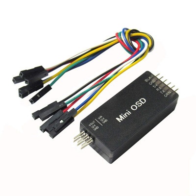

SPIDER Automation Mini OSD for APM 2.6 & APM 2.8 | ATmega328P MAVLink FPV Video Telemetry Overlay Module
The SPIDER Automation Mini OSD for APM 2.6 and APM 2.8 is a compact on-screen display module designed to overlay flight telemetry information onto a compatible FPV video feed. It is based on an ATmega328P 8-bit microcontroller with an Arduino bootloader and a dedicated MAX7456 monochrome OSD controller. The module is designed to work with compatible ArduPilot Mega flight controllers and MAVLink telemetry streams, allowing supported flight information to be viewed directly through the aircraft’s video system.
During operation, the Mini OSD receives telemetry data from the connected flight controller and combines supported information with the composite video signal from an onboard camera. The resulting video can be transmitted through a compatible wireless video transmitter and displayed on an FPV monitor or video receiver system. This arrangement provides access to flight telemetry without requiring a laptop or Mission Planner display during flight.
The board incorporates separate digital and analogue power sections, independent power indicators, solder-selectable power and ground connections, and a PAL video configuration jumper. Its FTDI-compatible programming interface and exposed HSYNC and LOS test points provide additional access for firmware programming and signal-level inspection.
Key Features
- ATmega328P 8-Bit Microcontroller: Arduino-bootloader-based processing platform for the Mini OSD firmware and telemetry handling.
- MAX7456 Monochrome OSD IC: Dedicated video overlay controller for generating monochrome on-screen information.
- MAVLink Protocol Support: Designed to receive compatible MAVLink telemetry data from ArduPilot-based flight controllers.
- APM Compatibility: Intended for APM 2.6 and APM 2.8 installations, with additional compatibility identified for APM 2 and APM 2.5.
- Composite Video Overlay: Adds supported telemetry information to a compatible camera video feed.
- FPV Telemetry Display: Enables flight information viewing through a compatible FPV video receiver and display.
- Independent Digital and Analogue Power Sections: Separates the digital processing supply arrangement from the analogue video-stage supply arrangement.
- Dual Power LEDs: Provides a separate indicator for each power section.
- Selectable Power and Ground Connections: Solder jumpers allow the two power sections to be electrically combined when required.
- FTDI-Compatible Interface: Supports programming and firmware access through a compatible 6-pin FTDI cable.
- ISP Programming Header: Provides an unpopulated standard 6-pin ISP header footprint.
- PAL Video Jumper: Provides a solder-selectable PAL video configuration option.
- HSYNC Test Point: Exposes the horizontal synchronisation signal for testing and diagnostics.
- LOS Test Point: Provides access to the loss-of-signal monitoring point.
- Compact PCB Assembly: Designed for integration into space-constrained flight-control and FPV electronics installations.
Microcontroller & OSD Processing Architecture
The Mini OSD combines an ATmega328P microcontroller with a MAX7456 monochrome on-screen display controller. The ATmega328P handles the module’s firmware and telemetry-processing functions, while the MAX7456 is responsible for generating the video overlay. The Arduino bootloader provides the programming foundation for compatible firmware workflows.
- Microcontroller: ATmega328P.
- Processor Architecture: 8-bit AVR.
- Bootloader: Arduino bootloader.
- OSD Controller: MAX7456.
- Display Technology: Monochrome on-screen video overlay.
- Telemetry Processing: Designed for compatible MAVLink data received from an APM flight controller.
MAVLink Telemetry & APM Integration
The Mini OSD is designed as a companion telemetry display for compatible ArduPilot Mega flight controllers. It receives MAVLink data through the flight-controller telemetry connection and uses the OSD circuitry to overlay supported flight information onto the camera video feed.
When connected to a compatible onboard camera and video transmission system, the module allows the operator to monitor available telemetry through an FPV display. The displayed information depends on the connected flight controller, the MAVLink data being transmitted and the installed OSD firmware configuration.
- Flight Controller Interface: Designed for compatible APM flight-controller telemetry connections.
- Communication Protocol: MAVLink.
- Video Integration: Overlays supported telemetry information onto a compatible composite video feed.
- FPV Monitoring: Provides an in-video telemetry display for compatible FPV installations.
- Mission Planner Alternative: Allows supported flight information to be viewed through the FPV video system without continuously viewing a laptop display.
Monochrome Video Overlay System
The integrated MAX7456 provides the monochrome OSD video-processing function. It combines supported character-based telemetry information with a compatible incoming composite video signal, allowing flight data to appear over the camera image.
- OSD Processing: MAX7456-based monochrome video overlay.
- Video Input: Intended for a compatible composite camera video signal.
- Video Output: Provides the overlaid video signal for connection to compatible FPV video equipment.
- PAL Configuration: Dedicated solder jumper supports PAL video configuration.
- Signal Monitoring: Exposed HSYNC and LOS test points support signal inspection.
Dual Power Architecture & Electrical Isolation
The board uses two independent power and ground sections to separate the digital processing circuitry from the analogue video-stage circuitry. The digital section supplies the ATmega328P and digital OSD circuitry, while the analogue section supplies the video-stage circuitry through its regulated 5V arrangement.
The design includes solder jumpers that allow the two power sections and their grounds to be combined when required by the installation. This configurable arrangement provides flexibility when integrating the OSD with different flight-controller and video-system power layouts.
- Digital Power Section: Provides +5V power for the ATmega328P and digital OSD circuitry.
- Digital Supply Sources: Can be powered through the FTDI connection or another suitable +5V source.
- Analogue Power Section: Uses a regulated +5V supply arrangement for the analogue video stage.
- Analogue Supply Connection: Receives power through the video input/output header arrangement.
- Video-Section Input Capability: The design description identifies support for an input supply up to +12V to the regulated analogue section.
- Independent Power Indicators: One LED indicator is provided for each power section.
- Power-Combining Jumpers: Solder jumpers allow the digital and analogue power sections to be combined when required.
- Ground-Combining Jumpers: The corresponding ground sections can also be connected through the provided solder-jumper arrangement.
Programming Interface & Development Access
The Mini OSD provides an FTDI-compatible programming connection for supported firmware operations. Its Arduino bootloader-based ATmega328P architecture supports compatible programming workflows using the appropriate interface cable. A separate standard 6-pin ISP header footprint is also provided, although the header is not populated.
- FTDI Interface: Compatible 6-pin programming pinout.
- Arduino Bootloader: Supports compatible bootloader-based programming procedures.
- ISP Header: Standard 6-pin ISP footprint, unpopulated.
- Firmware Access: Requires a compatible programming cable and supported firmware tools.
Signal Test Points & Video Configuration
The board exposes dedicated test points for selected video synchronisation and signal-monitoring functions. These provide access for electrical inspection and troubleshooting during integration or development.
- HSYNC Test Point: Provides access to the horizontal synchronisation signal.
- LOS Test Point: Provides access to the loss-of-signal monitoring point.
- PAL Selection Jumper: Allows the supported PAL video configuration to be selected through solder-jumper settings.
Applications
- APM 2.6 Telemetry Display: Video-based telemetry integration with compatible APM 2.6 flight controllers.
- APM 2.8 Telemetry Display: On-screen flight information integration with compatible APM 2.8 systems.
- ArduPilot FPV Systems: MAVLink telemetry overlay for compatible ArduPilot-based aircraft.
- APM 2 Flight-Control Systems: OSD integration with compatible APM 2 hardware.
- APM 2.5 Installations: Telemetry display integration with compatible APM 2.5 flight controllers.
- FPV Camera Systems: Combining supported flight information with a compatible onboard camera video feed.
- Wireless Video Transmission: Sending video with telemetry overlays through a compatible FPV video transmitter.
- Remote Flight Monitoring: Viewing available MAVLink flight information through a remote video display.
- Composite Video OSD Projects: MAX7456-based monochrome video overlay integration.
- Aircraft Telemetry Systems: Video-based display of supported flight-controller telemetry data.
- Arduino-Based OSD Development: Firmware development and configuration using the ATmega328P and compatible programming interface.
- FPV Electronics Integration: Compact OSD installation alongside compatible flight controllers, cameras and video equipment.
Package Includes
- 1 × Mini OSD for APM 2.6 & APM 2.8
- 1 × Set of Female-to-Female Jumper Cables
Product Specifications
| Parameter | Specification |
|---|---|
| Product Name | Mini OSD for APM 2.6 & APM 2.8 |
| Product Type | MAVLink On-Screen Display Module |
| Main Microcontroller | ATmega328P |
| Microcontroller Architecture | 8-bit AVR |
| Bootloader | Arduino bootloader |
| OSD Controller IC | MAX7456 |
| Display Type | Monochrome on-screen video overlay |
| Communication Protocol | MAVLink |
| Primary Flight Controller Compatibility | APM 2.6 and APM 2.8 |
| Additional APM Compatibility | APM 2 and APM 2.5 |
| Digital Supply | +5V DC |
| Digital Supply Sources | FTDI cable or another suitable +5V source |
| Analogue Section Supply | Regulated +5V DC |
| Analogue Section Input Capability | Up to +12V input to the regulated section |
| Power Sections | Two independent digital and analogue sections |
| Power Indicators | Two independent LED indicators |
| Power Configuration | Solder jumpers for combining power sections |
| Ground Configuration | Solder jumpers for combining ground sections |
| Programming Interface | FTDI-compatible 6-pin interface |
| ISP Header | Standard 6-pin footprint, unpopulated |
| Video Configuration | PAL selection solder jumper |
| Signal Test Points | HSYNC and LOS |
| Dimensions (L × W × H) | 58 × 22 × 12mm |
Connection & Operating Recommendations
- Verify Flight Controller Compatibility: Confirm the exact APM hardware revision and MAVLink telemetry configuration before connecting the Mini OSD.
- Check the Telemetry Connection: Verify the flight-controller telemetry port, signal wiring, connector orientation and ground reference before applying power.
- Separate Power Sections: Understand the digital and analogue supply arrangement before wiring the board. Do not assume that both sections are powered from the same connection.
- Check the +5V Digital Supply: Provide a suitable regulated +5V source for the ATmega328P and digital OSD circuitry.
- Verify Analogue Input Voltage: The video-stage supply arrangement is described as accepting up to +12V before regulation. Confirm the correct input pins and wiring before applying any voltage above 5V.
- Configure Power Jumpers: Combine the digital and analogue power or ground sections only when required by the system wiring and power architecture.
- Connect the Video Signal Correctly: Route the camera composite video signal through the OSD input and connect the overlay output to compatible video transmission equipment.
- Match Video Format: Set the PAL configuration jumper according to the video system and confirm compatibility with the connected camera and display equipment.
- Use a Compatible FTDI Cable: Check the 6-pin pinout and voltage levels before connecting a programming cable.
- Protect the ISP Header: The 6-pin ISP footprint is unpopulated. Any programming connection through this interface requires the appropriate header and correct pin mapping.
- Verify Firmware Compatibility: Use firmware intended for the ATmega328P Mini OSD and the connected APM/MAVLink configuration.
- Test Before Flight: Confirm telemetry reception, video pass-through, overlay visibility and power-indicator operation before installing the system for flight.