
SPIDER Automation | 2WD Smart Robot Car Chassis Kit with Speed Encoders | 3–6V Dual-Shaft BO Geared Motor Platform
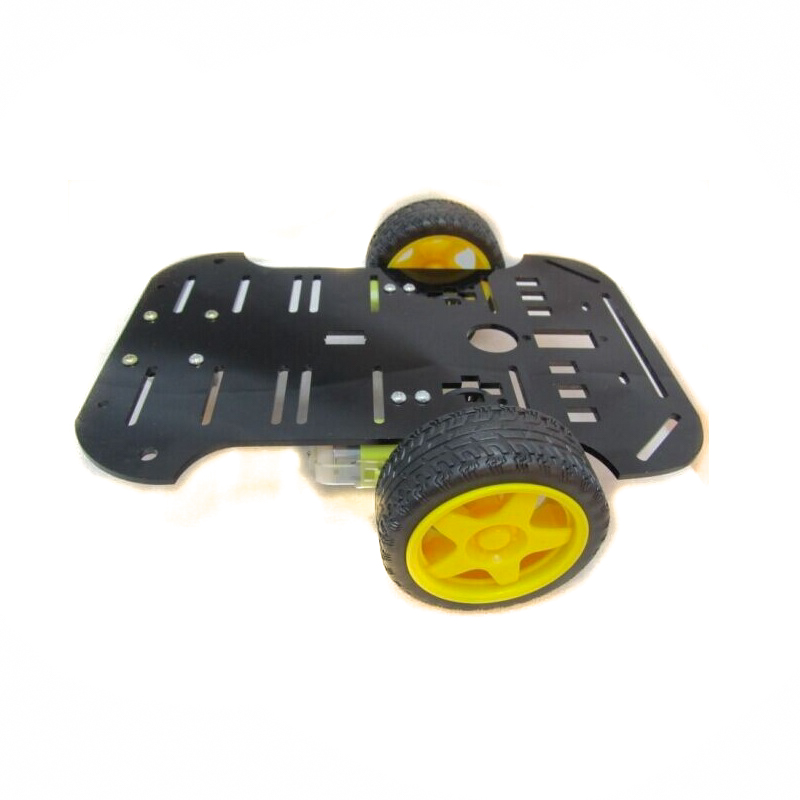
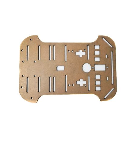
The SPIDER Automation 2WD Smart Robot Car Chassis Kit is a mechanical drive platform for developing compact programmable mobile robots. It combines a 200 × 140mm black acrylic chassis, two dual-shaft BO geared DC motors, two rubber-grip drive wheels and a universal caster wheel. The motors feature a 1:48 gear reduction ratio and support 3–6V DC operation, with specified no-load speeds of approximately 90 RPM at 3V and 200 RPM at 6V.
The kit also includes two speed encoder assemblies for developing rotational feedback and motor-speed measurement functions. With suitable sensing electronics and controller programming, encoder signals can be used for speed monitoring, distance estimation and motion-control applications. The open chassis arrangement provides a mounting base for compatible microcontrollers, motor drivers and additional sensor modules. A four-AA battery holder and the required mechanical fasteners are included; AA batteries and electronic control boards are not included.
Product Overview & Mechanical Design
The chassis is constructed from black acrylic and measures 200 × 140mm. It provides the structural mounting platform for the two geared motors, drive wheels, universal caster and additional compatible electronics. Its two-wheel-drive arrangement uses the powered wheels for propulsion and the caster wheel as an additional support point.
The kit is supplied with the main mechanical components and mounting hardware required for chassis assembly. Its modular arrangement allows the user to integrate suitable controller boards, motor driver circuits and sensing modules according to the intended robot design.
Dual-Shaft BO Geared Motor System
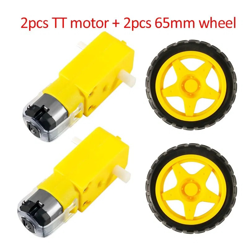
The drive system uses two dual-shaft BO geared DC motors. Each motor incorporates a gearbox with a 1:48 reduction ratio, providing the specified low-speed geared output for the robot’s wheel-drive arrangement. The dual-shaft configuration also provides an additional shaft interface suitable for the supplied encoder arrangement.
The motors operate within a stated 3–6V DC range. Their specified no-load speed changes with the applied voltage, while the stated current values represent no-load operation rather than loaded running or startup current.
- Motor Quantity: Two BO geared DC motors.
- Shaft Configuration: Dual-shaft motor design.
- Gear Reduction: 1:48.
- Operating Voltage: 3–6V DC.
- No-Load Speed at 3V: 90 RPM ±10%.
- No-Load Speed at 6V: 200 RPM ±10%.
- No-Load Current at 3V: Less than 150mA per motor.
- No-Load Current at 6V: Less than 200mA per motor.
Speed Encoder & Motion Measurement
The kit includes two speed encoder assemblies intended for rotational feedback from the drive system. When connected to compatible sensing electronics, encoder signals can be processed by a microcontroller to monitor motor rotation and support motion-measurement functions.
Encoder feedback can form the basis of several control functions:
- Motor-Speed Measurement: Monitoring rotational speed using encoder pulse information and suitable timing calculations.
- Distance Estimation: Estimating wheel rotation and travelled distance after the encoder pulse count is calibrated against the wheel configuration.
- Motion Feedback: Providing rotational information for programmed movement-control routines.
- Wheel Synchronisation: Supporting comparison of left and right motor rotation during controlled movement.
Actual measurement resolution and distance accuracy depend on the encoder’s pulse configuration, sensor electronics, wheel dimensions, calibration and control software. A specific pulses-per-revolution value is not provided for this kit.
Wheel & Chassis Support Configuration
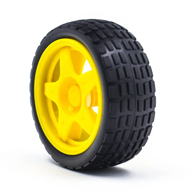
The robot uses two 65 × 25mm plastic wheels with rubber tyre grips for powered movement. The rubber contact surface provides the wheel-to-ground interface, while the universal caster wheel provides an additional support point for the chassis.
- Drive Wheels: Two plastic wheels with rubber tyre grips.
- Wheel Dimensions: 65mm diameter × 25mm width.
- Support Wheel: One universal caster wheel.
- Chassis Dimensions: 200 × 140mm.
- Chassis Material: Black acrylic.
Power Supply Arrangement
A four-AA battery holder is included for the robot’s battery-mounting arrangement. Four 1.5V alkaline AA cells provide a nominal combined battery voltage of 6V when connected in series, which falls within the stated 3–6V motor operating range. The batteries are not included.
The battery holder supplies the physical battery arrangement, but the complete robot’s power distribution and controller connections must be configured according to the electrical requirements of the selected control board and motor driver. Motor startup and loaded current can exceed the stated no-load current, so the power source and driver should be selected with suitable current capacity.
Applications
The encoder-equipped 2WD chassis can be integrated with compatible electronics to develop mobile robot prototypes and motion-control systems.
- Arduino-Based Mobile Robots: Building programmable two-wheel-drive robot platforms using a compatible Arduino controller.
- Encoder-Based Speed Monitoring: Developing motor RPM measurement functions using the supplied encoder assemblies and suitable sensing electronics.
- Distance Measurement: Estimating robot movement from calibrated wheel rotation and encoder feedback.
- Wheel-Speed Control: Developing programmed motor-speed adjustment and feedback-based movement routines.
- Two-Wheel Differential Drive: Implementing independent left and right motor control for forward, reverse and turning movements.
- Obstacle-Avoidance Robots: Integrating compatible ultrasonic or infrared distance sensors with programmed motor responses.
- Line-Following Robot Platforms: Adding compatible line sensors for track detection and programmed navigation.
- Embedded Control Prototyping: Integrating microcontrollers, motor drivers and rotational feedback hardware on a compact chassis.
- Mobile Sensor Platforms: Mounting compatible sensors and electronic modules for movement-based data collection.
- Robotics Engineering Demonstrations: Demonstrating geared motor operation, encoder feedback, differential drive and embedded motion control.
Package Includes
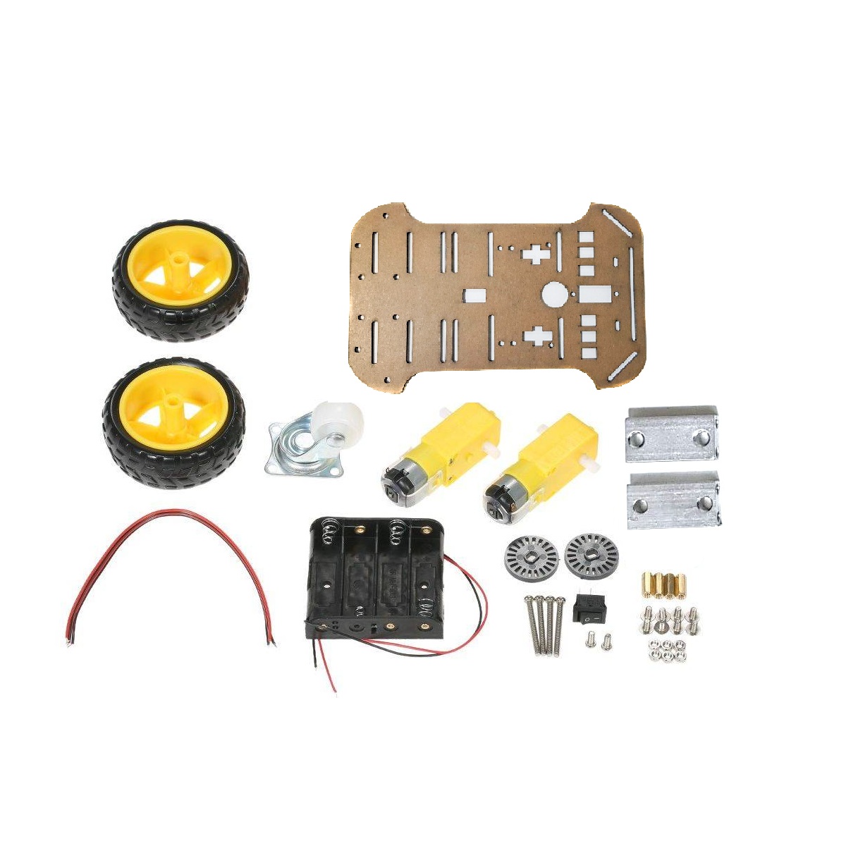
- Robot Car Chassis: 1 unit.
- Dual-Shaft BO Geared Motors: 2 units.
- Robot Wheels: 2 units, plastic with rubber tyre grips.
- Universal Caster Wheel: 1 unit.
- Speed Encoder Assemblies: 2 units.
- Four-AA Battery Holder: 1 unit.
- Screws and Nuts: Required assembly hardware.
Not Included: Four AA batteries, controller board, motor driver module and additional sensors or electronic expansion modules.
Product Specifications
| Parameter | Specification |
|---|---|
| Product Type | Smart robot car chassis kit |
| Drive Configuration | 2WD, two-wheel drive |
| Chassis Dimensions | 200 × 140mm |
| Chassis Material | Acrylic |
| Chassis Colour | Black |
| Motor Type | BO geared DC motor |
| Motor Quantity | 2 units |
| Motor Shaft Configuration | Dual shaft |
| Motor Operating Voltage | 3–6V DC |
| Gear Reduction Ratio | 1:48 |
| No-Load Speed at 3V | 90 RPM ±10% |
| No-Load Speed at 6V | 200 RPM ±10% |
| No-Load Current at 3V | Less than 150mA per motor |
| No-Load Current at 6V | Less than 200mA per motor |
| Motor Encoder Configuration | Encoder-equipped dual-shaft motor arrangement |
| Speed Encoder Quantity | 2 units |
| Encoder Function | Rotational feedback for speed and movement measurement with compatible electronics |
| Wheel Quantity | 2 drive wheels |
| Wheel Dimensions | 65mm diameter × 25mm width |
| Wheel Material | Plastic |
| Tyre Grip Material | Rubber |
| Additional Support Wheel | 1 universal caster wheel |
| Battery Holder | Four-AA battery holder |
| Battery Requirement | 4 × AA cells; not included |
| Nominal Voltage with Four 1.5V Cells in Series | 6V nominal |
| Assembly Hardware | Screws and nuts included |
| Shipping Weight | 0.35kg |
| Shipping Dimensions | 27 × 15 × 2cm |
Installation & Operating Recommendations
- Assemble the Chassis: Mount the motors, wheels and universal caster using the supplied screws and nuts. Ensure the chassis is properly aligned before tightening the fasteners.
- Check Wheel Alignment: Verify that both drive wheels rotate freely and that the caster wheel can move without obstruction.
- Connect the Motor Driver: Use a compatible motor driver between the controller and BO motors. Select a driver with suitable voltage and current capacity for motor startup and loaded operation.
- Use the Correct Supply: Keep the motor supply within the specified 3–6V DC operating range. Verify battery polarity and power connections before switching on the system.
- Connect Encoder Sensors: Connect the encoder assemblies to compatible sensing inputs and configure the controller program to process the feedback signals.
- Calibrate Motion Measurement: Establish the encoder pulse count and effective wheel circumference through testing before using calculated distance or speed values.
- Test Motor Direction: Perform an initial low-risk drive test with the wheels clear of the ground. Reverse motor wiring or adjust the control program as required to obtain the intended direction.
- Secure Electronics: Mount the controller, motor driver and sensors firmly, keeping wires away from the wheels, shafts and moving components.
- Monitor Motor Loading: The stated current figures are no-load values. Avoid prolonged motor stalling or operation under excessive mechanical load.
- Inspect Periodically: Check wheel grip, motor mounting, encoder alignment, fasteners and wiring during routine maintenance.