
SPIDER Automation | QFN24 to DIP-24 PCB Adapter Board | Dual-Sided 0.5mm & 0.65mm QFN-to-DIP Conversion
The SPIDER Automation QFN24 to DIP-24 Adapter Board is a dual-sided surface-mount package adapter designed to convert compatible 24-pin QFN integrated circuits into a DIP-24-style connection arrangement. It addresses a common electronics development requirement: interfacing compact QFN components with circuit platforms and prototyping setups that use conventional 2.54mm-pitch connections.
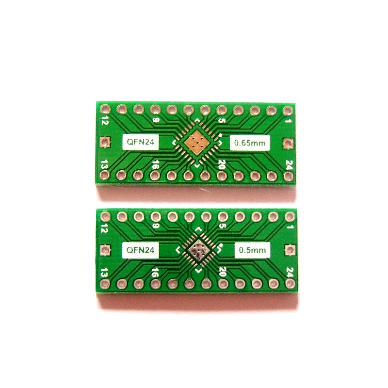
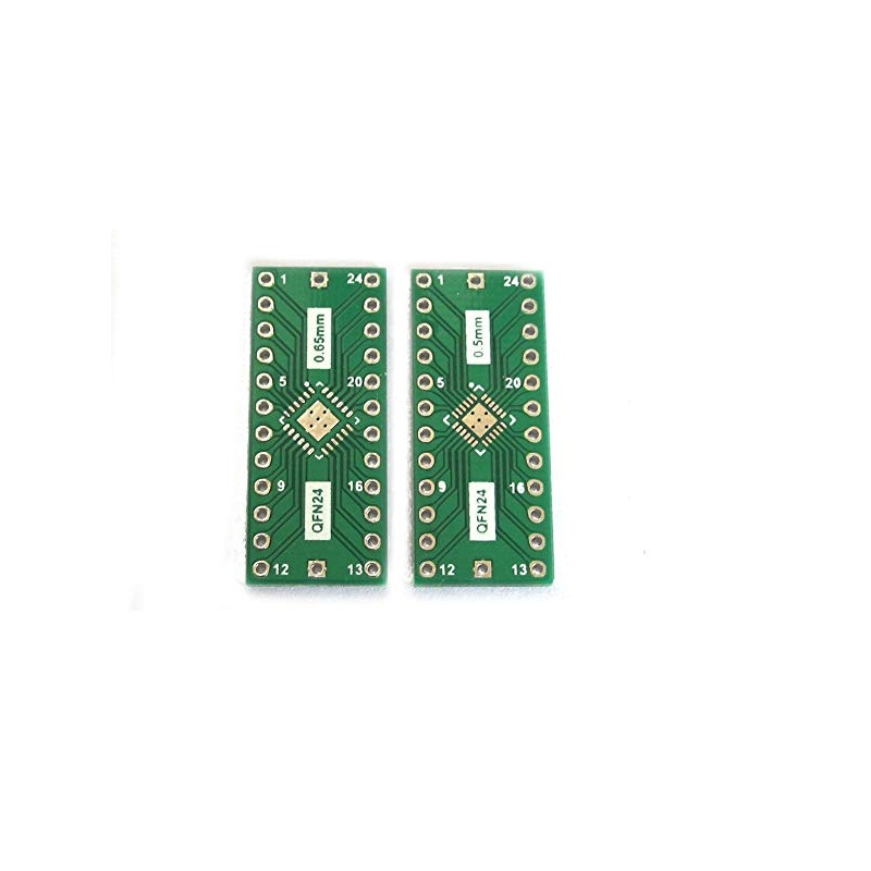
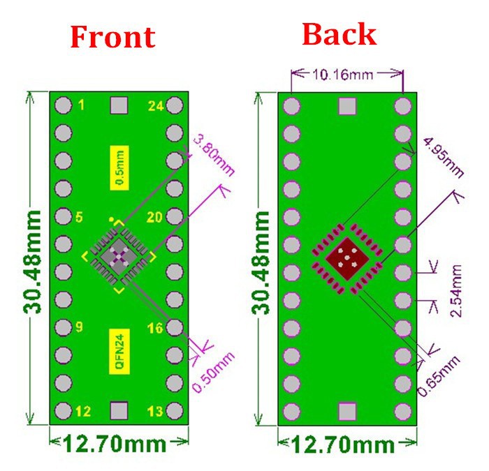
The PCB incorporates two alternative QFN footprint configurations, with a 0.5mm QFN pitch on one side and a 0.65mm QFN pitch on the reverse side. Both configurations provide a conversion path to a 24-pin DIP-compatible layout with 2.54mm pitch. This arrangement makes the board useful for evaluating compatible QFN devices, assembling prototypes and integrating selected SMD components into development circuits without creating a dedicated adapter layout for each supported pitch.
Product Overview & Conversion Design
QFN components use compact surface-mount terminations and generally require a PCB footprint designed for their package dimensions and terminal arrangement. The adapter provides an intermediate PCB interface between a compatible QFN24 package and a DIP-24-style connection layout.
- QFN24 input footprint: Supports compatible 24-terminal QFN packages using either of the two footprint configurations provided on the board.
- Dual-sided pitch selection: The two PCB faces provide separate 0.5mm and 0.65mm QFN footprint options.
- DIP-24 output arrangement: Routes the selected package footprint to a 24-pin DIP-compatible layout with 2.54mm pitch.
- Prototype integration: Provides a practical interface for incorporating supported QFN devices into suitable DIP-oriented development circuits.
Technical Features & Functional Characteristics
- Two QFN pitch configurations: Supports 0.5mm and 0.65mm QFN terminal pitch options on opposite sides of the PCB.
- 24-pin package support: Designed around compatible 24-pin QFN package footprints and a DIP-24-style output arrangement.
- Standard 2.54mm output pitch: Provides a conventional DIP-compatible spacing for interfacing with suitable through-hole prototyping and circuit connections.
- Compact PCB dimensions: The 31 × 13.5mm board format is suitable for compact electronics development and evaluation setups.
- Low-profile construction: The 1.6mm board thickness provides a slim PCB adapter format.
- Reusable development interface: Can be incorporated into component evaluation and prototype workflows when the QFN package and electrical pin mapping are compatible.
Applications
The QFN24 to DIP-24 adapter is intended for electronics engineering and development tasks involving compatible 24-pin QFN integrated circuits. Typical applications include:
- QFN IC Prototyping: Adapting supported QFN24 devices for use in DIP-oriented prototype circuit assemblies.
- SMD Component Evaluation: Providing a DIP-compatible interface for evaluating selected surface-mount integrated circuits.
- Electronics Development: Integrating compatible QFN components into experimental circuit designs and development setups.
- PCB Interface Adaptation: Bridging supported QFN surface-mount footprints to conventional 2.54mm-pitch connection arrangements.
- IC Testing & Debugging: Supporting test arrangements for compatible QFN24 devices when used with suitable external test equipment.
- Through-Hole Prototyping: Connecting selected QFN devices to compatible DIP-style prototyping platforms.
- Component Replacement Evaluation: Facilitating the evaluation of compatible QFN IC alternatives in existing DIP-oriented development circuits.
- Electronics Laboratory Work: Supporting component-level experimentation, circuit verification and engineering development activities.
Package Includes
- 1 × QFN24 to DIP-24 Dual-Sided PCB Adapter Board
Product Specifications
| Parameter | Specification |
|---|---|
| Product Type | QFN-to-DIP PCB Adapter Board |
| Primary Function | Conversion of compatible QFN24 packages to a DIP-24-style connection layout |
| QFN Package Pin Count | 24 pins |
| Output Package Format | DIP-24 compatible layout |
| Output Pin Count | 24 pins |
| PCB Configuration | Dual-sided, with alternative QFN footprints |
| Side A QFN Pitch | 0.5mm |
| Side B QFN Pitch | 0.65mm |
| DIP Output Pitch | 2.54mm |
| Board Length | 31mm |
| Board Width | 13.5mm |
| Board Thickness | 1.6mm |
| Product Weight | Approximately 3g |
| Package Quantity | 1 adapter board |
Connection & Operating Recommendations
- Verify the QFN footprint: Before soldering, confirm that the IC has 24 terminals and that its package pitch matches the selected 0.5mm or 0.65mm footprint.
- Select the correct PCB side: Use the 0.5mm or 0.65mm footprint as appropriate for the target IC. Do not assume that the two sides support interchangeable package dimensions.
- Check package dimensions and pin mapping: Confirm the IC body dimensions, terminal arrangement, pin-1 orientation and electrical pinout against the component datasheet before assembly.
- Use suitable SMD soldering methods: QFN installation requires appropriate soldering equipment and controlled alignment. Ensure that all terminals make the intended electrical connections.
- Inspect the assembled board: Check for solder bridges, open connections, misalignment and unintended shorts before applying power.
- Verify DIP-side compatibility: Confirm the required 2.54mm connection arrangement and mating interface before integrating the adapter into a socket, breadboard or prototype circuit.
- Observe IC electrical requirements: The adapter provides a PCB connection conversion only; it does not regulate voltage, provide signal conditioning or protect the IC from incorrect power and signal connections.