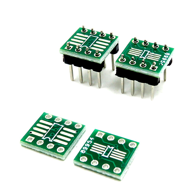

SPIDER Automation SO/MSOP/TSSOP/SOIC/SOP8 to DIP8 Breakout Adapter Board (Pack of 5)
The SPIDER Automation SO/MSOP/TSSOP/SOIC/SOP8 to DIP8 Breakout Adapter Board (Pack of 5) is an indispensable prototyping accessory designed for electronics engineers, repair technicians, and hobbyists working with surface-mount integrated circuits. Operational amplifiers, 555 timer ICs, and memory chips are frequently manufactured exclusively in surface-mount SOIC and TSSOP packages, making them impossible to plug directly into standard breadboards for rapid circuit design and testing. This dual-sided adapter board solves that challenge effortlessly.
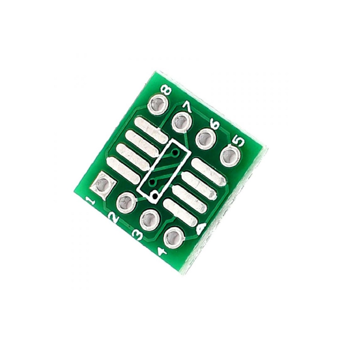
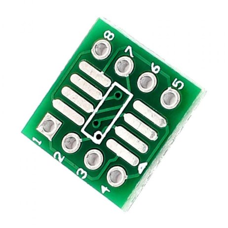
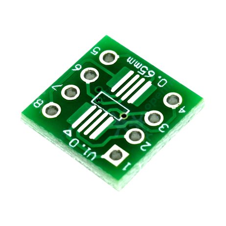
Engineered with a practical dual-sided layout, the PCB adapter accommodates a wide variety of 8-pin surface-mount package types. Side A features a 1.27mm pin spacing pattern suitable for common SO8, SOP8, and SOIC8 packages, while Side B features a 0.65mm pin spacing pattern suitable for SSOP8, TSSOP8, and MSOP8 encapsulations. Measuring 12 mm in length by 12 mm in width, the breakout board converts fine-pitch surface-mount silicon into standard through-hole DIP8 connections. Whether you are building rapid prototype circuits or testing custom components on a breadboard using jumper wires, this reusable adapter provides a clean, robust, and reliable solution. Note: Header pins are not included in the package.
Dual-Sided Layout Architecture & Breadboard Prototyping
The core mechanical and electrical advantage of the SO8/TSSOP8 to DIP8 Adapter lies in its versatile dual-sided trace routing. Fine-pitch surface-mount pins require careful trace routing; this breakout board routes each SMT pad cleanly to standard 0.1-inch (2.54mm) through-hole pin rows along the perimeter.
By soldering your surface-mount IC onto the appropriate side’s landing pads and attaching standard header pins or jumper wires to the through-hole rows, the entire assembly transforms into a standard DIP8 IC. This allows you to insert the chip into standard breadboards for solderless prototyping, mount it onto through-hole project boards, or wire it directly into experimental setups without tedious soldering and desoldering.
Technical Features & Functional Characteristics
- Dual-Side 8-Pin SMT Support: Side A supports 1.27mm pitch SO8, SOP8, and SOIC8 packages; Side B supports 0.65mm pitch SSOP8, TSSOP8, and MSOP8 packages.
- Multi-Pin Compatibility: Each board features 8 pins, fully compatible with 4-pin, 6-pin, and 8-pin surface-mount chips.
- Standard 2.54mm DIP Pin Spacing: Converts fine-pitch pads into standard through-hole DIP format with 0.1-inch spacing for breadboard use.
- Convenient Pack of 5 Boards: Value bundle provides five identical adapter plates for multiple project builds and lab testing.
- Compact & Ultra-Light Footprint: Measures just 12 × 12 mm for minimal space consumption in experimental circuits.
- Reusable Prototyping Accessory: Eliminates dead-bug wiring and allows surface-mount ICs to be reused across multiple projects.
System Compatibility & Laboratory Applications
The SPIDER Automation SO8/TSSOP8 Adapter is widely utilized across various electronic development and repair environments:
- Operational Amplifier Prototyping: Testing surface-mount single, dual, and quad op-amps on solderless breadboards.
- Timer & Memory IC Testing: Mounting surface-mount 555 timers, EEPROMs, and logic chips into breadboard circuits.
- Electronics Repair & Modding: Creating drop-in replacement DIP modules for obsolete or hard-to-find surface-mount ICs.
- Educational & Maker Workshops: Teaching students how to solder surface-mount components and bridge SMT parts to standard through-hole circuits.
Package Includes
- 5 × SO / MSOP / TSSOP / SOIC / SOP8 to DIP8 PCB Adapter Boards
Product Specifications
| Parameter | Specification |
|---|---|
| Product Category | Surface Mount (SMT) Breakout Adapter / IC Conversion PCB Board |
| Supported IC Packages | SO8, SOP8, SOIC8, SSOP8, TSSOP8, MSOP8 (4-Pin, 6-Pin, and 8-Pin Chips) |
| Side A Specifications | 1.27 mm Pin Spacing for SO8 / SOP8 / SOIC8 Packages to DIP8 Upright |
| Side B Specifications | 0.65 mm Pin Spacing for SSOP8 / TSSOP8 / MSOP8 Packages to DIP8 Upright |
| Output Conversion Format | DIP8 Through-Hole Package Format (2.54 mm / 0.1 Inch Pin Spacing) |
| Patch Pitch | 0.4 mm Surface Mount Patch Pitch |
| PCB Dimensions | 12 mm × 12 mm |
| Board Construction | Double-Sided Glass-Fiber Circuit Board |
| Unit Net Weight | Approx. 1 g each (5 g total for 5-pack) |
| Operating Temperature Range | -40°C to +85°C Industrial Environmental Tolerance |
| Gross Shipping Weight | 0.001 kg (1 gram) |
| Shipping Package Dimensions (L × W × H) | 7 cm × 5 cm × 1 cm |
Installation & Soldering Guidelines
Follow these best practices when assembling your SO8/TSSOP8 adapter boards:
- Package Verification: Select the correct side of the double-sided adapter board matching your specific IC package type (Side A for 1.27mm pitch SOIC/SOP or Side B for 0.65mm pitch SSOP/TSSOP/MSOP).
- IC Alignment: Carefully align pin 1 of your surface-mount integrated circuit with the pin 1 indicator dot or silkscreen marking on the selected side of the adapter PCB.
- SMT Soldering: Apply liquid flux to the landing pads. Tack-solder two opposing corner pins to secure the chip, then carefully solder all fine-pitch pins using a fine-tip soldering iron.
- Header Pin / Wire Attachment: Solder standard break-away header pins or jumper wires into the perimeter through-holes corresponding to standard 2.54mm breadboard spacing.
- Continuity Inspection: Inspect all soldered joints under magnification (or use a digital multimeter in continuity mode) to check for solder bridges between adjacent fine-pitch pins prior to testing.