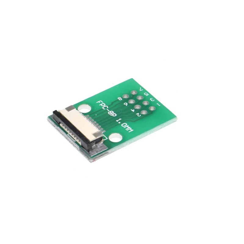

SPIDER Automation | FPCA1T254-8 8-Pin FFC/FPC Adapter Board | 1.0mm to 2.54mm PCB Interconnection
The FPCA1T254-8 FFC/FPC Adapter Board is an eight-position interface board designed to connect a compatible 1.0mm-pitch flexible flat cable (FFC) or flexible printed circuit (FPC) to a PCB connection arrangement using 2.54mm × 2.54mm through-hole spacing. It addresses a common electronic integration requirement: connecting compact flexible-cable assemblies to circuit boards that use a more conventional terminal layout.
Flexible cables are frequently used where a thin, compact interconnection is required between electronic modules, particularly display assemblies and space-constrained circuit sections. The FPCA1T254-8 provides an intermediate adapter format for bringing an eight-contact flexible-cable interface into a different PCB connection pitch. This simplifies the interconnection layout when the cable and receiving circuit board use different contact-spacing arrangements.
Product Overview & Interface Design
The adapter is configured around two distinct connection-spacing requirements: a 1.0mm pitch on the FFC/FPC side and a 2.54mm × 2.54mm through-hole spacing on the PCB side. The difference between these layouts allows a fine-pitch flexible cable interface to be incorporated into an electronic assembly designed around conventional through-hole connection spacing.
Its eight-pin configuration is intended for compatible eight-contact cable interfaces. Correct selection depends on matching the cable’s conductor count, 1.0mm pitch, contact orientation and connection geometry with the adapter. The board provides a passive interconnection path; it does not perform signal amplification, voltage conversion or communication-protocol translation.
Technical Features & Integration Benefits
- Fine-Pitch Cable Termination: The 1.0mm interface pitch accommodates compatible FFC/FPC cable assemblies used in compact electronic modules.
- Conventional PCB Spacing: The 2.54mm × 2.54mm through-hole arrangement supports integration with circuit layouts designed around standard through-hole spacing.
- Eight-Contact Configuration: Provides an eight-position interconnection format for compatible cable and circuit-board arrangements.
- Display Module Interfacing: Helps connect flexible-cable display assemblies to a separate PCB connection layout.
- Space-Conscious Integration: Supports electronic designs in which flexible-cable routing and compact module connections are important.
- Corrosion-Resistance Feature: The product is specified with high corrosion resistance, making connection-environment suitability an important consideration during component selection.
Applications
The FPCA1T254-8 can be incorporated into electronic assemblies that require an eight-contact, 1.0mm-pitch FFC/FPC connection to interface with a 2.54mm-spaced PCB layout, subject to matching cable geometry and electrical requirements.
- Display Module Interconnection: Connecting compatible display FFC/FPC cables to a separate PCB interface.
- Embedded Display Electronics: Integrating compact display assemblies into embedded control boards.
- Communication Equipment: Interconnecting flexible-cable modules within communication-system electronics.
- Automotive Electronics: Supporting flexible-cable interconnections in compatible automotive electronic assemblies.
- Consumer Electronics: Connecting compact internal modules that use 1.0mm-pitch flexible cables.
- Electronic Control Boards: Bringing a fine-pitch cable connection into a PCB assembly designed around 2.54mm through-hole spacing.
- Compact Instrumentation: Interfacing display or other flexible-cable modules within space-conscious measurement and instrumentation equipment.
- PCB Prototyping and Integration: Evaluating compatible FFC/FPC module connections with a conventional through-hole PCB layout.
Package Includes
- 1 × FPCA1T254-8 8-Pin FFC/FPC Adapter Board, 1.0mm to 2.54mm
Product Specifications
| Parameter | Specification |
|---|---|
| Model Number | FPCA1T254-8 |
| Product Type | FFC/FPC Adapter Board |
| Connector Interface | FFC/FPC to PCB connection |
| Number of Pins | 8 pins |
| FFC/FPC Pitch | 1.0mm |
| Through-Hole Spacing | 2.54mm × 2.54mm |
| PCB Connection Type | Through-hole spacing arrangement |
| Adapter Function | 1.0mm FFC/FPC interface to 2.54mm PCB connection spacing |
| Corrosion Resistance | High corrosion resistance |
| Package Quantity | 1 piece |
| Package Contents | 1 × 8-pin FFC/FPC adapter board |
Connection & Operating Recommendations
- Verify Cable Compatibility: Before installation, confirm that the flexible cable has eight conductors and a 1.0mm contact pitch. Also check cable width, exposed-contact orientation and insertion geometry against the adapter interface.
- Confirm PCB Footprint: Check the receiving PCB layout against the 2.54mm × 2.54mm through-hole spacing before preparing the board or soldering connections.
- Check Electrical Pin Mapping: Verify the function and order of all eight connections against the cable and target circuit documentation. Do not assume that pin numbering or signal order is identical across different FFC/FPC assemblies.
- Use Controlled Soldering: Apply suitable soldering temperature and dwell time for the board and its connection points. Avoid excessive heat or mechanical force that could damage the adapter or nearby circuitry.
- Inspect Cable Contacts: Ensure the flexible cable contacts are clean, correctly aligned and fully engaged with the mating interface before powering the assembly.
- Provide Cable Strain Relief: Route the flexible cable without sharp folds, excessive tension or repeated bending immediately beside the connection point.
- Verify Electrical Ratings: Confirm the voltage, current and signal requirements of the connected circuit before operation. The adapter’s pitch and pin count alone do not establish its electrical ratings.