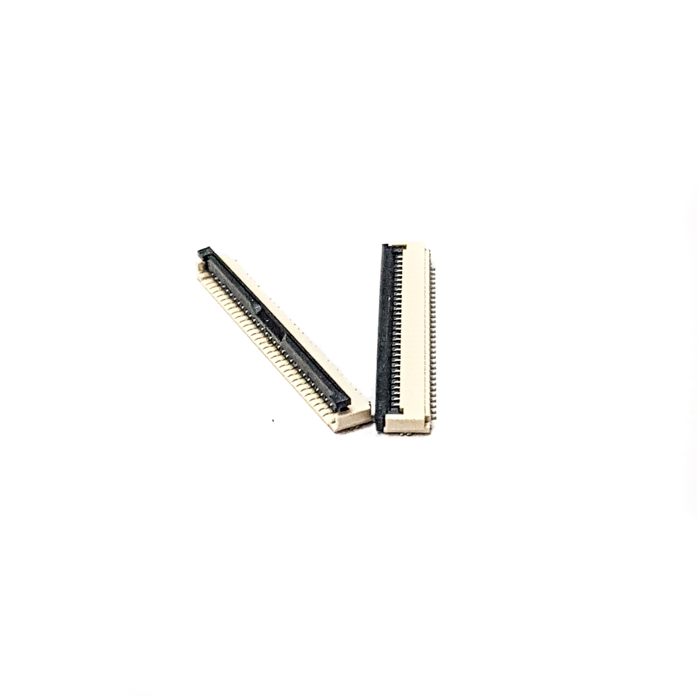
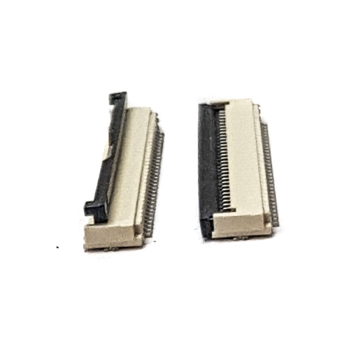

SPIDER Automation | 0.5mm Pitch 30-Pin FFC/FPC SMT Flip-Lock Connector | Fine-Pitch Flexible Cable Interface
The 0.5mm Pitch 30-Pin FFC/FPC SMT Flip-Lock Connector is designed to establish a compact, detachable electrical connection between a flexible flat cable (FFC) or flexible printed circuit (FPC) and a printed circuit board. With 30 contact positions arranged at 0.5mm pitch, it accommodates multi-conductor flexible-cable interfaces while maintaining a narrow connector footprint. This configuration is particularly relevant to display assemblies and electronic modules where numerous signal connections must pass through a limited PCB area.
The connector uses a flip-lock actuator to facilitate cable installation: the actuator is opened for cable insertion and closed to retain the flexible cable in its mating position. Its strengthened actuator design, phosphor bronze contacts and Nylon 46 UL94-V0 insulation provide the principal mechanical and material characteristics of the assembly. The connector is specified for 50V and 0.5A operation and an operating temperature range of −25°C to +85°C, making correct electrical and mechanical matching important during equipment design and maintenance.
Product Overview & Functional Design
FFC and FPC connections are commonly used to carry multiple electrical signals between closely positioned electronic assemblies. The 30-pin arrangement provides a single compact interface for a group of conductors, helping reduce the space required for separate wire connections. A 0.5mm pitch places adjacent contacts closely together, making the connector suitable for dense PCB layouts used in compact displays, instrumentation and electronic control equipment.
The flip-lock mechanism provides access to the cable-contact area during installation. With the actuator open, the correctly oriented flexible cable can be inserted into the connector. Closing the actuator retains the cable at the contact interface, establishing the electrical connection between the cable conductors and the PCB-mounted connector contacts. This arrangement also allows the cable to be released for servicing or replacement without desoldering the connector from the PCB.
Technical Features & Material Construction
- 30-Position Contact Arrangement: Accommodates a 30-conductor flexible-cable interface, allowing multiple signals to be routed through one compact connector location.
- 0.5mm Fine Pitch: Provides closely spaced contacts for high-density interconnection where PCB area is limited.
- Flip-Lock Actuator: Provides an open-and-close cable-retention mechanism for inserting, securing and releasing compatible FFC/FPC cables.
- Strengthened Actuator Design: The reinforced flip-lock feature is intended to improve the actuator’s mechanical handling characteristics during normal cable installation and servicing.
- Phosphor Bronze Contacts: Forms the conductive contact system that interfaces with the individual cable conductors.
- Nylon 46 UL94-V0 Insulation: The connector’s insulating material carries a UL94-V0 flammability classification, an important material property for electronic component selection.
- Metal and Plastic Construction: Combines conductive contact components and insulating structural material within a compact connector assembly.
- Surface-Mount PCB Installation: Uses an SMD/SMT mounting configuration for integration into surface-mount electronic assemblies.
- Specified Electrical Capacity: The stated 50V voltage and 0.5A operating-current ratings define key electrical selection parameters for the interface.
- Wide Operating Temperature Range: The specified −25°C to +85°C range supports component selection for electronic assemblies operating across varied ambient conditions.
Electrical Interface & PCB Integration
The connector provides a 30-way electrical interface between the flexible cable and PCB. Its 0.5mm contact pitch requires a matching FFC/FPC cable with the correct conductor count, contact spacing, cable width and exposed-contact arrangement. The cable’s exposed contacts must face the connector’s contact side; matching the pitch alone is not sufficient to establish compatibility.
As an SMD/SMT component, the connector is intended for surface-mount assembly on a compatible PCB footprint. The board layout must account for the connector’s terminal arrangement and mechanical mounting geometry. During circuit design, the 50V and 0.5A ratings should be considered alongside the actual signal type, current demand and operating conditions of the connected equipment.
Applications
This connector is intended for compact electronic equipment requiring a detachable, multi-conductor FFC/FPC interface. Its 30-pin configuration and fine contact pitch make it relevant to the following integration requirements:
- Display Module Connections: Connecting compatible 30-contact display FFC/FPC cables to display controller or interface PCBs.
- Embedded Display Assemblies: Routing multiple display signals between a display panel and its associated processing or control board.
- Control Panel Electronics: Providing flexible-cable interconnection between display sections and internal control circuitry.
- Communication Equipment: Connecting compact electronic modules that use multi-conductor flexible cable interfaces.
- Automotive Electronic Assemblies: Supporting compatible internal FFC/FPC connections in compact vehicle electronic equipment.
- Consumer Electronic Devices: Interconnecting internal display and circuit-board assemblies where space-efficient cable termination is required.
- Medical Electronic Equipment: Providing a compact internal cable interface in compatible electronic instruments and display assemblies.
- Instrumentation Systems: Connecting display, interface or control subassemblies through a detachable 30-way flexible cable.
- Electronic Manufacturing: Integrating fine-pitch flexible-cable connections into surface-mount PCB assemblies.
- Equipment Repair and Maintenance: Replacing a damaged or worn connector on a compatible PCB where the original footprint and cable interface match.
Package Includes
- 4 × 0.5mm Pitch 30-Pin FFC/FPC SMT Flip-Lock Connectors
Product Specifications
| Parameter | Specification |
|---|---|
| Product Type | FFC/FPC Connector |
| Connector Configuration | Flip-lock connector |
| Number of Pins | 30 |
| Pin Spacing / Pitch | 0.5mm |
| Mounting Type | Surface Mount (SMD/SMT) |
| Actuator Type | Flip-lock, strengthened actuator design |
| Rated Voltage | 50V |
| Operating Current | 0.5A |
| Contact Material | Phosphor bronze |
| Insulation Material | Nylon 46 UL94-V0 |
| Overall Construction | Metal and plastic |
| Available Colours | Beige, Black |
| Insulation Resistance | 800 MΩ |
| Operating Temperature | −25°C to +85°C |
| Length | 19mm |
| Width | 2mm |
| Height | 5mm |
| Approximate Weight | 1g per connector |
| Package Quantity | 4 pieces |
Connection & Operating Recommendations
- Match the Flexible Cable: Confirm the cable has 30 conductors and a 0.5mm pitch. Check its overall width, thickness and contact exposure before installation.
- Verify Contact Orientation: Check whether the cable’s exposed contacts face the correct direction for the connector’s internal contact arrangement. Incorrect orientation can prevent proper electrical connection.
- Operate the Flip-Lock Carefully: Open the actuator using controlled pressure at the designated moving section. Avoid levering against the connector body or applying excessive force to the hinge area.
- Insert the Cable Evenly: Keep the cable aligned with the connector entry and insert it straight to the intended engagement position. Avoid angled insertion or lateral movement that could damage fine-pitch contacts.
- Secure the Actuator: Close the flip-lock fully and evenly after cable insertion. Do not force the actuator if the cable is misaligned or obstructed.
- Follow the PCB Footprint: Use a PCB layout compatible with the connector’s SMT terminal arrangement. Maintain alignment during placement and soldering to prevent displaced or bridged contacts.
- Use Controlled Rework: Apply suitable temperature control and handling methods during soldering or replacement. Excessive heat can damage the insulating housing or actuator assembly.
- Provide Cable Support: Route the flexible cable without sharp creases or excessive pulling force. Support the cable so that vibration or movement does not continuously load the connector interface.
- Check Electrical Requirements: Confirm that the connected circuit operates within the connector’s 50V and 0.5A specified ratings, and verify that the actual signal and load requirements are suitable.
- Inspect Before Power-Up: Check cable seating, actuator closure, solder joints and adjacent contacts for alignment or bridging before energising the assembly.