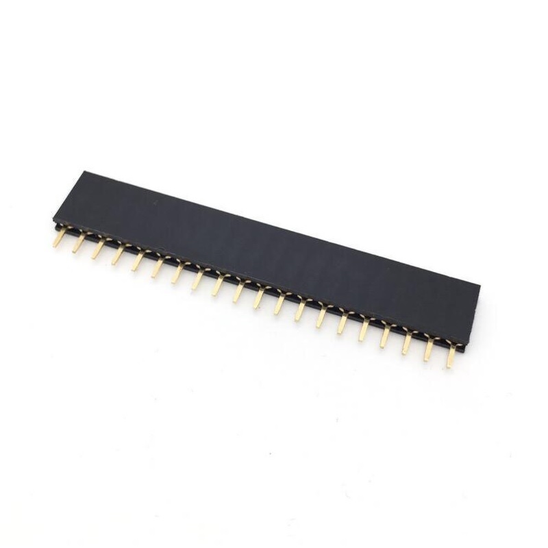
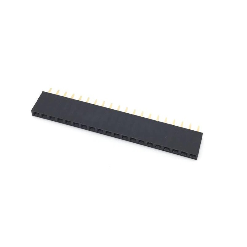

SPIDER Automation | 2.54mm 1×20 Pin Female Single-Row Straight Header Strip | PCB Socket Connector
The 2.54mm 1×20 Pin Female Single-Row Straight Header Strip is a multi-position PCB socket connector designed to establish detachable electrical connections with compatible male pin headers. It provides 20 female contact positions arranged in a single straight row, with a centre-to-centre pitch of 2.54mm. This commonly used spacing makes it relevant to electronic assemblies that require organised board-to-board, module-to-board or component-interface connections.
Unlike a permanent soldered wire connection, a female header provides a mating socket interface that accepts corresponding male header pins. This arrangement allows compatible electronic modules and circuit boards to be installed, removed or replaced without desoldering the individual connection points. The product is specified for SMT/SMD mounting and has an approximate weight of 0.8g per strip. Correct selection requires matching the contact pitch, row arrangement, mating-pin geometry and PCB mounting footprint.
Product Overview & Connector Design
The header consists of a single row of 20 female contacts arranged at 2.54mm intervals. Each socket is intended to receive a compatible male pin, creating an individual electrical connection within the larger 20-position interface. The linear arrangement provides a consistent connection sequence that can be used for multiple signal lines, supply connections or other circuit interconnections, depending on the electrical design.
The straight configuration maintains the contacts in a linear arrangement rather than an angled or dual-row layout. This is useful when the mating connector and PCB footprint are designed for a straight single-row interface. The detachable mating arrangement also supports modular electronics, where a connected board may need to be removed for inspection, replacement or configuration changes.
Technical Features & Integration Benefits
- 20 Female Contact Positions: Provides twenty individual socket contacts for multi-line electrical interconnection through one connector strip.
- Single-Row 1×20 Arrangement: Keeps all contact positions in one linear row, supporting organised PCB layouts and matching male-header configurations.
- 2.54mm Contact Pitch: Uses 2.54mm centre-to-centre spacing, a common header format in electronic circuit and module interconnections.
- Straight Configuration: Provides a straight mating arrangement for applications designed around linear female header placement.
- Female Socket Contacts: Accept compatible male header pins, enabling detachable connections between electronic assemblies.
- SMT/SMD Mounting Designation: Identifies the specified mounting category for PCB integration; the actual terminal geometry must be checked against the intended footprint.
- Modular Connection Interface: Allows compatible boards or modules to be disconnected and replaced without individually removing soldered wires.
- Lightweight Construction: Has an approximate weight of 0.8g per strip for compact electronic assemblies.
Electrical & Mechanical Integration
The 20-position arrangement can be used to route multiple independent electrical connections between compatible boards or modules. Each contact corresponds to a position in the mating male header, allowing the circuit designer to allocate the required signals and supply connections across the row. The connector itself does not define a fixed pinout, voltage rating or current rating; these depend on the electrical characteristics of the selected connector and the complete circuit.
For mechanical integration, the 2.54mm pitch and single-row geometry must match the mating male header. The specified SMT/SMD mounting category should also be checked against the actual terminal arrangement and recommended PCB footprint. A matching pitch alone does not guarantee mating compatibility, since pin dimensions, socket geometry, contact depth and mounting configuration also affect the fit.
Applications
This 1×20 female header strip is suitable for electronic assemblies requiring a straight, single-row, 2.54mm-pitch socket interface. Typical applications include:
- PCB-to-PCB Interconnection: Providing a detachable 20-position connection between compatible circuit boards.
- Development Board Interfaces: Connecting compatible expansion boards and electronic modules through standard-pitch male headers.
- Embedded Control Electronics: Routing multiple control, input or output connections between a controller board and an auxiliary module.
- Sensor Interface Boards: Connecting multi-line sensor modules to a compatible control or data-acquisition PCB.
- Display Interface Assemblies: Providing a detachable header connection for display-related boards designed with a matching 20-position male interface.
- Communication Modules: Connecting compatible communication boards to their host circuit through a multi-contact header arrangement.
- Power and Signal Distribution: Providing separate contact positions for circuit connections where the selected electrical ratings are suitable.
- Industrial Electronic Assemblies: Supporting modular connections between compatible control and interface circuit boards.
- Electronic Prototyping: Building removable board connections during circuit evaluation and development.
- Equipment Repair and Replacement: Replacing a damaged female header where the original pitch, row configuration, mounting style and mating geometry match.
Package Includes
- 5 × 2.54mm 1×20 Pin Female Single-Row Straight Header Strips
Product Specifications
| Parameter | Specification |
|---|---|
| Product Type | Female Header Strip |
| Connector Gender | Female |
| Contact Arrangement | Single row |
| Pin Configuration | 1×20 |
| Number of Pins | 20 |
| Pin Spacing / Pitch | 2.54mm |
| Connector Orientation | Straight |
| Mounting Type | SMD/SMT (as specified) |
| Mating Interface | Compatible 2.54mm-pitch male pin header |
| Product Weight | Approximately 0.8g per strip |
| Package Quantity | 5 pieces |
| Package Contents | 5 × 1×20 pin female single-row straight header strips |
Installation & Operating Recommendations
- Verify Mating Header Compatibility: Use a male header with matching 2.54mm pitch, pin dimensions and contact arrangement. Confirm the socket geometry and insertion depth before assembly.
- Check the PCB Footprint: Verify the connector’s actual SMT terminal layout and recommended land pattern before designing or manufacturing the PCB.
- Align the Single Row: Position the connector parallel to the corresponding PCB footprint so that all twenty contacts align with their intended pads.
- Use an Appropriate Soldering Process: Follow a suitable surface-mount soldering process for the actual connector construction. Avoid excessive heat or mechanical force during installation.
- Inspect Contact Alignment: Check that the connector is seated evenly and that adjacent solder joints are free from unintended bridges or poor connections.
- Confirm Pin Mapping: Verify the intended electrical function of each of the twenty positions against the circuit schematic before connecting powered equipment.
- Insert the Mating Header Carefully: Keep the male header aligned with the female sockets and apply even insertion pressure. Avoid angled insertion that could deform the contacts.
- Check Electrical Ratings: Establish suitable voltage and current limits from the connector’s verified electrical specifications and the requirements of the complete circuit.
- Support Connected Modules: Avoid using the header as a structural support for heavy boards or cables. Provide suitable mechanical support where the connected assembly may experience movement or vibration.