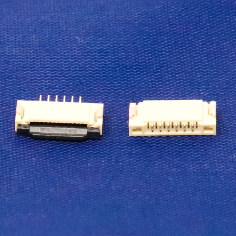
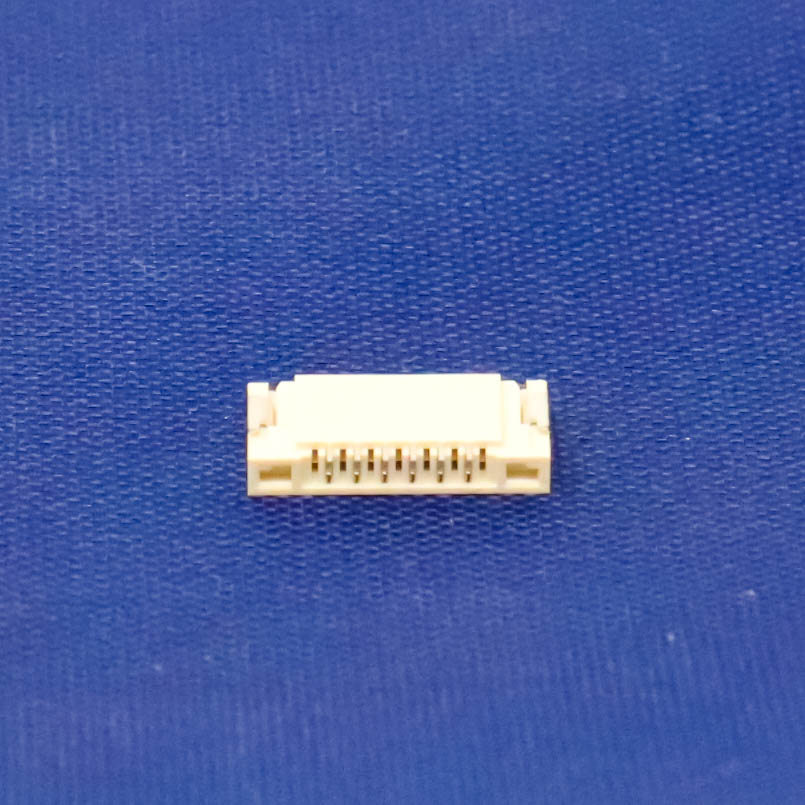

SPIDER Automation | 1mm Pitch 6-Pin FFC/FPC Flip-Lock Connector | SMT Flexible Cable Interface
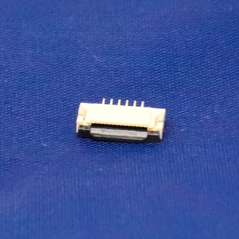
The 1mm Pitch 6-Pin FFC/FPC Flip-Lock Connector is a surface-mount PCB connector designed to establish a compact electrical interface between a flexible flat cable (FFC) or flexible printed circuit (FPC) and a printed circuit board. Its six-contact configuration provides separate connection positions within a small footprint, making it suitable for display interfaces, internal signal connections and electronic assemblies that use flexible cables instead of conventional wire harnesses. The 1mm contact pitch defines the spacing between adjacent contacts and is a key consideration when selecting the mating cable and designing the PCB footprint.
The connector incorporates a flip-lock actuator that opens to allow the flexible cable to be inserted and closes to retain it against the contact interface. Its contact system is made from phosphor bronze, while the insulating housing uses Nylon 46 UL94-V0. With a rated voltage of 50V, operating current of 0.5A and operating temperature range of −25°C to +85°C, it provides defined electrical and environmental parameters for compatible electronic assemblies. The compact body measures approximately 11 × 2 × 5mm and is intended for surface-mount PCB integration.
Product Overview & Functional Design
FFC/FPC connectors provide a direct termination point for flexible circuits, allowing multiple conductors to connect to a PCB through a single compact interface. This six-pin version supports six electrical paths arranged at 1mm intervals. It can therefore be used where a flexible cable carries a group of display, control or other electronic signals between a board and a connected module.
The flip-lock actuator provides access to the cable insertion slot when opened. After the compatible cable is aligned and inserted to the required depth, the actuator is closed to retain the cable and establish contact with the connector terminals. This arrangement allows the flexible cable to be disconnected for servicing or assembly without permanently soldering the cable conductors to the PCB. The strengthened actuator is designed to support the cable-retention operation, while careful handling helps protect the small locking component from damage.
Technical Features & Construction
- Six-Position Contact Layout: Provides six electrical connection points for compatible FFC/FPC cable assemblies.
- 1mm Contact Pitch: Defines the centre-to-centre spacing between adjacent contacts and supports compact multi-conductor connections.
- Flip-Lock Cable Actuator: Opens for cable insertion and closes to retain the cable against the contact interface.
- Strengthened Actuator Design: Reinforced flip-lock construction supports practical cable installation and removal when operated correctly.
- SMT Mounting: Designed for surface-mount assembly on a compatible PCB land pattern.
- Phosphor Bronze Contact Material: Forms the conductive contact interface for transferring electrical signals or power between the flexible cable and PCB.
- Nylon 46 Insulating Housing: Provides insulation and mechanical positioning for the contact arrangement.
- UL94-V0 Flammability Classification: The specified insulation material carries a UL94-V0 flammability classification.
- Metal and Plastic Construction: Combines conductive metal contacts with an insulating polymer housing.
- Compact Connector Body: Approximately 11 × 2 × 5mm, supporting integration into space-constrained PCB assemblies.
Electrical Characteristics
The connector has a rated voltage of 50V and an operating current rating of 0.5A. Its stated insulation resistance is 800MΩ, and its operating temperature range is −25°C to +85°C. These ratings provide key selection parameters for compatible low-voltage electronic connections. Actual circuit suitability should also account for the connected cable, PCB layout, thermal conditions and the electrical requirements of the complete assembly.
The supplied contact-resistance figure is expressed as 20MΩ maximum. This unit is unusually high for a connector contact-resistance specification and may represent a transcription error, so it is not treated as a confirmed electrical performance value.
FFC/FPC Cable Compatibility & PCB Integration
Select a flexible cable with six conductors and 1mm pitch to match the connector’s contact arrangement. Cable compatibility also depends on parameters beyond pin count and pitch, including cable thickness, overall width, exposed-contact length, contact-side orientation and insertion geometry. These dimensions and the contact arrangement must match the connector before installation to ensure correct alignment and engagement.
For PCB integration, use the appropriate SMT footprint for the connector’s terminal arrangement. Allow sufficient board access to operate the flip-lock actuator and insert or remove the flexible cable. During PCB assembly, maintain accurate component alignment and suitable soldering conditions to prevent terminal displacement or damage to the connector housing.
Applications
This six-position flexible-cable connector is suitable for electronic assemblies that require a compact, detachable connection between a PCB and an FFC/FPC cable.
- Display Modules: Flexible cable connections between compatible display assemblies and their controller or interface boards.
- LCD Control Boards: Multi-conductor connections for display signals and associated electronic interfaces.
- Embedded Systems: Internal flexible-cable interconnections in compact embedded electronic equipment.
- Automotive Electronic Modules: Compact PCB-to-flexible-cable connections in compatible electronics operating within the specified temperature range.
- Communication Equipment: Flexible circuit interfaces in compact communication and electronic control assemblies.
- Medical Electronic Instruments: Internal display and signal connections in compatible electronic instrumentation.
- Consumer Electronics: Flexible cable termination in compact devices where board space and internal cable routing are important.
- Control and Operator Interfaces: Connections between display, input and control circuit boards using compatible flexible circuits.
- Portable Electronic Equipment: Space-efficient internal cable connections in compact equipment assemblies.
Package Includes
- 2 × 1mm Pitch 6-Pin FFC/FPC SMT Flip-Lock Connectors
Product Specifications
| Parameter | Specification |
|---|---|
| Product Type | FFC/FPC Connector |
| Connector Configuration | 6-Pin, 6-Position |
| Contact Pitch | 1mm |
| Connector Interface | FFC/FPC |
| Actuator Type | Flip-Lock |
| Actuator Construction | Strengthened Flip-Lock Actuator |
| Mounting Type | Surface Mount (SMD/SMT) |
| Rated Voltage | 50V |
| Operating Current | 0.5A |
| Contact Material | Phosphor Bronze |
| Insulation Material | Nylon 46 |
| Flammability Classification | UL94-V0 |
| Housing Construction | Metal and Plastic |
| Insulation Resistance | 800MΩ |
| Contact Resistance | 20MΩ maximum (unit requires verification) |
| Operating Temperature | −25°C to +85°C |
| Connector Length | 11mm |
| Connector Width | 2mm |
| Connector Height | 5mm |
| Approximate Unit Weight | 1g per connector |
| Available Colours | Beige, Black |
| Package Quantity | 2 Pieces |
Installation & Operating Recommendations
- Verify Cable Compatibility: Use a six-conductor FFC/FPC cable with 1mm pitch. Confirm cable thickness, width, exposed-contact length and contact orientation before insertion.
- Open the Flip-Lock Actuator Carefully: Operate the actuator using its intended opening movement. Avoid excessive force, twisting or prying that could damage the locking component.
- Align the Flexible Cable: Position the cable evenly with its exposed contacts facing the connector’s contact side. Keep the cable straight during insertion.
- Insert to the Correct Depth: Ensure the cable is fully and evenly positioned in the insertion area before closing the actuator. Avoid folding or creasing the flexible circuit.
- Close the Actuator Evenly: Secure the cable by closing the flip-lock actuator without forcing it. Check for correct alignment if the actuator does not close normally.
- Follow the PCB Footprint: Use a compatible SMT land pattern and maintain accurate component positioning during soldering.
- Observe Electrical Ratings: Keep the circuit within the connector’s 50V rated voltage and 0.5A operating-current limits.
- Protect the Cable During Servicing: Open the actuator before removing the cable. Do not pull the flexible circuit while it is retained by the closed locking mechanism.
- Disconnect Power Before Handling: Switch off the connected circuit before inserting, removing or inspecting the flexible cable to reduce the risk of short circuits and contact damage.