
SPIDER Automation | FPCA1T254-10 10-Pin FFC/FPC Adapter Board | 1.0mm to 2.54mm PCB Interconnection
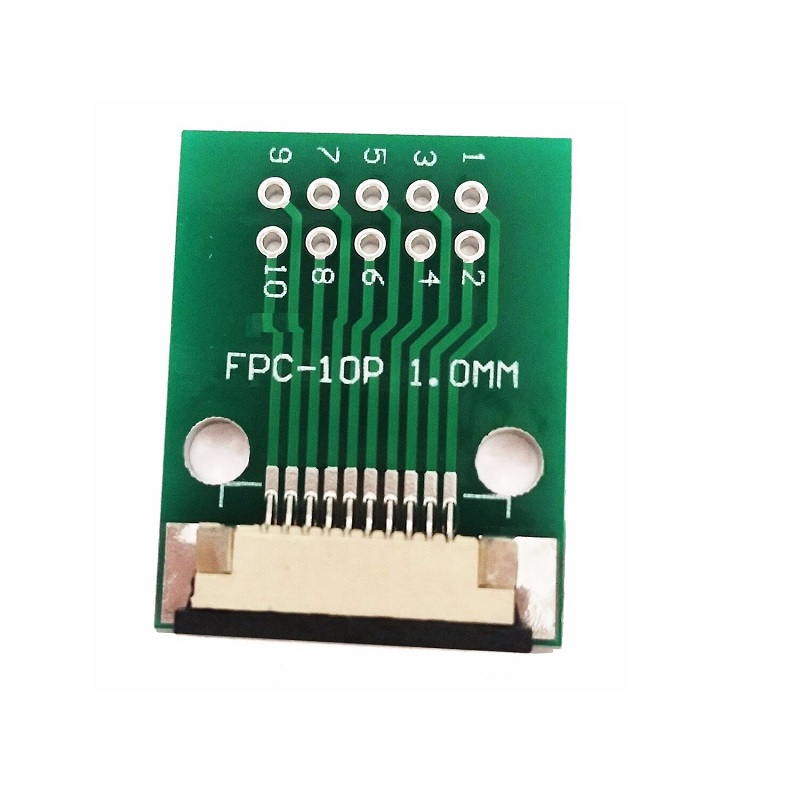
The SPIDER Automation FPCA1T254-10 FFC/FPC Adapter Board is a compact interconnection board designed to bridge a fine-pitch flexible cable interface and a conventional through-hole PCB connection layout. It provides a 10-pin, 1.0mm-pitch FFC/FPC interface alongside a board-side connection arrangement with 2.54mm × 2.54mm through-hole spacing. This allows compatible flexible-cable modules, including display assemblies, to be integrated into electronic circuits that use standard through-hole wiring and prototyping connections.
The adapter functions as a passive electrical routing interface: corresponding connections are brought from the flexible-cable side to the through-hole side for access by the surrounding circuit. It does not perform voltage conversion, signal amplification, signal conditioning or communication-protocol translation. With its defined 10-pin configuration and approximate weight of 3g, model FPCA1T254-10 provides a practical interconnection option for embedded electronics, display integration, PCB development and custom electronic assemblies.
Product Overview & Interface Design
Flexible flat cables and flexible printed circuits are frequently used where a thin, compact interconnection is required between electronic modules. Their fine contact spacing can differ from the connection spacing used by conventional through-hole circuit layouts. The FPCA1T254-10 adapter board provides an intermediate interface between these two connection formats.
On the cable side, the adapter is designed for a 10-position FFC/FPC connection with 1.0mm pitch. On the board side, it provides a through-hole arrangement with 2.54mm × 2.54mm spacing. This arrangement makes the flexible-cable connections accessible to compatible PCB wiring, prototyping and circuit-integration methods without requiring the fine-pitch cable contacts to be connected directly to a conventional through-hole layout.
Technical Features & Functional Characteristics
- 10-Pin Configuration: Provides a ten-position interconnection arrangement between the FFC/FPC interface and the board-side terminals.
- 1.0mm FFC/FPC Pitch: Designed for flexible cable interfaces with 1.0mm spacing between adjacent contacts.
- 2.54mm × 2.54mm Through-Hole Layout: Provides a conventional through-hole spacing arrangement for board-side connection and integration.
- Passive Interconnection: Routes electrical connections between corresponding interface positions without active electronic processing.
- Display Connection Support: Provides an accessible board-level interface for compatible flexible-cable display modules.
- Compact Adapter Format: Bridges different connection spacings within a single adapter-board assembly.
- Lightweight Construction: Approximate product weight is 3g, supporting use in compact electronic assemblies.
- Defined Model Identification: FPCA1T254-10 identifies the 10-pin, 1.0mm-to-2.54mm adapter configuration.
Electrical Interface & Connection Architecture
The adapter provides a physical electrical path between the flexible-cable contacts and the through-hole connection positions. Each connection is intended to carry the corresponding electrical path across the adapter, allowing the connected circuit to access the signals or supply connections provided by the attached FFC/FPC assembly.
The adapter is a passive interconnection component. It does not change signal voltage levels, regulate power, amplify signals or translate communication protocols. Electrical compatibility therefore depends on the connected module, cable pin assignment, PCB circuit and operating requirements of the complete system.
Before installation, verify the 10-position cable arrangement, 1.0mm pitch, cable width, thickness, exposed-contact orientation and insertion geometry. Also confirm the pin mapping between the flexible cable and the intended circuit connections. Matching pitch and pin count alone does not establish complete cable compatibility.
PCB Integration & Installation Considerations
The board-side interface uses a 2.54mm × 2.54mm through-hole spacing, allowing integration with compatible through-hole connection layouts. The adapter can be incorporated into a circuit assembly where flexible-cable connections need to be made accessible for wiring, prototyping or connection to another PCB interface.
When designing the PCB or mounting arrangement, verify the actual hole pattern, terminal layout and connection mapping against the adapter. The stated 2.54mm × 2.54mm spacing defines the through-hole arrangement; it should not be interpreted as a complete board outline or a substitute for a verified footprint drawing.
Applications
The FPCA1T254-10 adapter board is suitable for electronic designs that need to connect a compatible 1.0mm-pitch flexible cable to a 2.54mm through-hole interface. Typical applications include:
- Display Module Interfacing: Bringing compatible 10-pin FFC/FPC display connections out to a conventional through-hole connection layout.
- Display Controller Boards: Connecting flexible-cable display assemblies to compatible controller electronics.
- Embedded Electronic Systems: Integrating compact flexible-cable modules into through-hole-based circuit assemblies.
- PCB Prototyping: Making fine-pitch FFC/FPC connections accessible during circuit development and evaluation.
- Board-to-Board Interconnection: Supporting circuit connections between modules that use different connection formats.
- Custom Interface Boards: Providing a flexible-cable input interface for custom-designed PCB assemblies.
- Electronic Instrumentation: Connecting compatible internal display or electronic modules to measurement and control circuitry.
- Communication Equipment: Integrating compatible flexible-cable interfaces within compact communication electronics.
- Equipment Repair: Replacing or adapting a compatible flexible-cable connection when integrating a module into an existing circuit arrangement.
- Electronics Development: Evaluating compatible FFC/FPC-connected modules within conventional 2.54mm through-hole development setups.
Package Includes
- 1 × FPCA1T254-10 10-Pin FFC/FPC Adapter Board (1.0mm to 2.54mm)
Product Specifications
| Parameter | Specification |
|---|---|
| Product Type | FFC/FPC adapter board |
| Model Number | FPCA1T254-10 |
| Contact Configuration | 10-pin |
| Flexible Cable Interface | FFC/FPC |
| FFC/FPC Connector Pitch | 1.0mm |
| Board-Side Connection Type | Through-hole |
| Through-Hole Spacing | 2.54mm × 2.54mm |
| Interconnection Function | Passive electrical routing between FFC/FPC and through-hole interfaces |
| Approximate Product Weight | 3g |
| Package Quantity | 1 adapter board |
Connection & Operating Recommendations
- Confirm Cable Configuration: Use a compatible 10-position FFC/FPC cable with 1.0mm pitch. Check the cable width, thickness and contact arrangement before installation.
- Verify Contact Orientation: Confirm whether the exposed conductive contacts face the required direction for the adapter’s FFC/FPC interface before inserting the cable.
- Check Pin Mapping: Verify the relationship between each cable contact and its corresponding through-hole connection before connecting the adapter to the circuit.
- Insert the Cable Correctly: Align the flexible cable evenly with the connector interface and ensure that all contacts are properly engaged using the connector’s intended retention arrangement.
- Verify the Through-Hole Layout: Match the 2.54mm × 2.54mm spacing and actual terminal arrangement with the PCB or mounting interface before installation.
- Use Appropriate Soldering Practices: Make through-hole connections using a suitable soldering process and avoid excessive heat that could damage the board or connector assembly.
- Provide Cable Support: Route the flexible cable without sharp bends, twisting or unnecessary pulling near the connector interface.
- Disconnect Power During Assembly: Isolate the connected equipment before inserting, removing or modifying the flexible cable or board-side wiring.
- Verify Electrical Operation: Check continuity, pin mapping and connected-module operation before placing the assembly into service.