
SPIDER Automation | 2.54mm 2×20 Pin Female Header Strip | 40-Position Double-Row PCB Connector
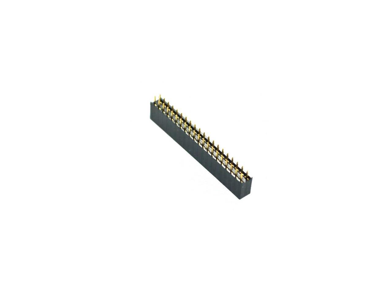
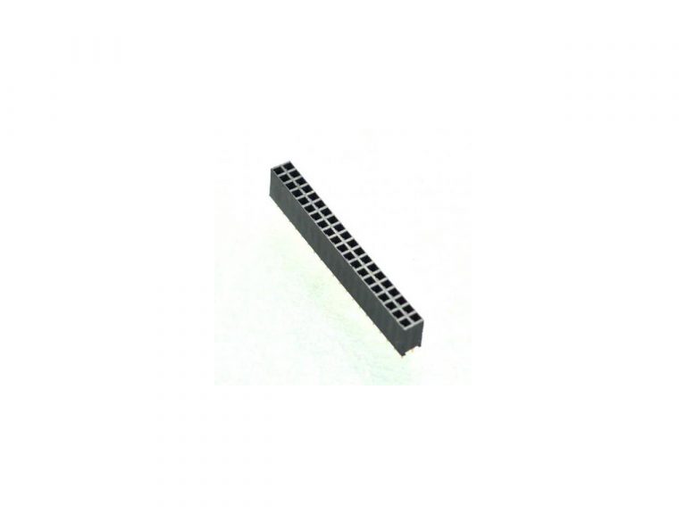
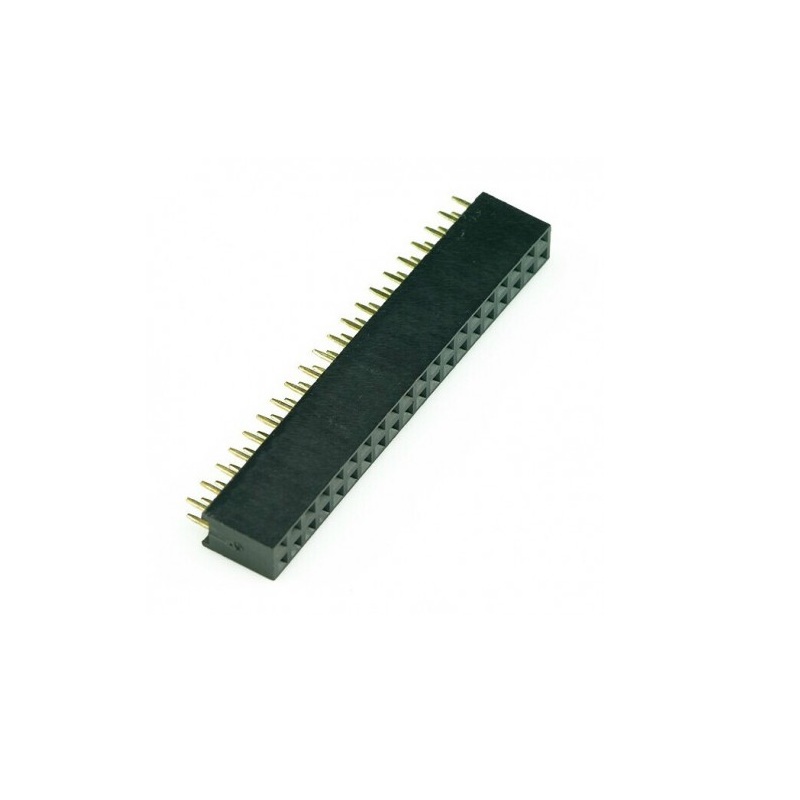
The SPIDER Automation 2.54mm 2×20 Pin Female Double-Row Header Strip is a through-hole PCB connector designed to establish a 40-position electrical interface between compatible circuit boards, electronic modules and male header assemblies. Its two-row arrangement provides 20 female socket positions per row, allowing multiple signal or power connections to be organised within a compact connector footprint. The female contact geometry accepts matching male header pins, making it useful where a removable or serviceable board-level connection is required.
The connector uses phosphor bronze contacts with a specified contact resistance of 20mΩ, housed in a PBT UL94V-0 insulating body. Its insulation resistance is rated at ≥1000MΩ. The standard 2.54mm pitch supports compatible dual-row PCB connector layouts, while the through-hole mounting arrangement allows the terminal pins to be soldered directly to a circuit board. With an overall size of 51 × 5 × 11.5mm, this 40-position socket strip provides a defined connection interface for electronic assemblies requiring organised multi-contact interconnection.
Product Overview & Functional Design
A female header strip functions as the socket side of a board-level connector pair. When a compatible male header is inserted, its pins engage the corresponding female contacts to establish electrical continuity across the connector positions. This arrangement can simplify the assembly of controller boards, expansion modules and interconnected PCBs by consolidating multiple electrical connections into one dual-row interface.
The 2×20 configuration provides 40 individual contact positions arranged in two parallel rows. This layout is useful for compact multi-signal interfaces where a single-row connector would require more board-edge length. The female socket format also supports disconnection and reconnection during module replacement, inspection or servicing, provided the mating connector and assembly are designed for the intended insertion cycles.
Technical Features & Material Characteristics
- Dual-Row 40-Position Interface: Two rows of 20 female contacts provide a consolidated connection point for compatible 40-pin male headers.
- 2.54mm Contact Pitch: Standard spacing supports integration with matching 2.54mm dual-row connector arrangements.
- Phosphor Bronze Contact Material: Provides the conductive contact elements used to establish electrical connections with mating male pins.
- 20mΩ Contact Resistance: Defines the specified resistance across the connector contact interface.
- PBT UL94V-0 Insulating Body: Separates adjacent contact positions and provides a mechanically defined insulating structure with a UL94V-0 flammability classification.
- ≥1000MΩ Insulation Resistance: Specifies the insulation resistance characteristic of the connector.
- Through-Hole Construction: Supports direct PCB mounting through soldered terminal connections.
- Compact Connector Envelope: The 51 × 5 × 11.5mm overall dimensions help engineers assess component placement and mechanical clearance.
Electrical Interface & PCB Integration
The connector provides a 40-position female interface for compatible dual-row male headers. For successful integration, the mating component must match the 2.54mm pitch, two-row arrangement, row spacing, pin dimensions and insertion geometry. The connector’s 2.54mm pitch alone does not establish compatibility with every 40-pin header, since different connector families can use different body profiles and mating dimensions.
The through-hole mounting format is intended for PCB layouts with matching plated or unplated mounting holes, as appropriate for the board design and terminal construction. During footprint design, account for the complete connector dimensions and verify the actual terminal arrangement rather than relying solely on the nominal pitch or overall body length.
Mechanical Design & Installation
The female socket body maintains the two contact rows in a fixed arrangement, helping position a matching male header during mating. Its 51mm length, 5mm width and 11.5mm height should be considered when planning board placement, enclosure clearance and access for connector insertion or removal.
For PCB assembly, position the connector squarely against the intended footprint and ensure all terminals align with their corresponding holes before soldering. Maintaining correct alignment helps prevent mechanical stress on the connector body and solder joints when a mating header is inserted.
Applications
This 2.54mm dual-row female header strip can be used in electronic assemblies that require a compatible 40-position socket interface.
- Microcontroller Interface Boards: Female socket connections for compatible controller-board headers and external interface circuits.
- Embedded Control Systems: Multi-position interconnections between embedded controller PCBs and supporting electronic modules.
- Development and Evaluation Boards: Socket interfaces for compatible expansion boards and test modules.
- PCB-to-PCB Connections: Removable electrical interconnection between circuit boards using matching dual-row male headers.
- Industrial Electronic Assemblies: Organised multi-contact connections within control and monitoring electronics.
- Signal Interface Modules: Consolidation of multiple signal paths through a single 40-position connector arrangement.
- Electronic Prototyping Assemblies: Through-hole socket installation in circuit designs requiring a compatible dual-row header interface.
- Test and Measurement Equipment: Connector interfaces for compatible internal boards, signal-conditioning modules and measurement electronics.
- Board Expansion Assemblies: Socket connections for add-on PCBs designed around the matching 2×20, 2.54mm header geometry.
- PCB Maintenance and Replacement: Removable board-level connections that facilitate module disconnection during servicing when the mating assembly permits it.
Package Includes
- 2.54mm 2×20 Pin Female Double-Row Header Strip: 5 pieces
Product Specifications
| Parameter | Specification |
|---|---|
| Product Type | Female Header Strip |
| Connector Gender | Female |
| Contact Configuration | 2×20 pins |
| Total Contact Positions | 40 |
| Number of Rows | 2 |
| Positions per Row | 20 |
| Pin Pitch | 2.54mm |
| Mounting Type | Through-Hole |
| Contact Material | Phosphor Bronze |
| Contact Resistance | 20mΩ |
| Insulation Material | PBT |
| Flammability Rating | UL94V-0 |
| Insulation Resistance | ≥1000MΩ |
| Length | 51mm |
| Width | 5mm |
| Height | 11.5mm |
| Weight per Piece | Approximately 3g |
| Package Quantity | 5 pieces |
Installation & Operating Recommendations
- Verify Mating Connector: Confirm that the male header has a matching 2×20 arrangement, 2.54mm pitch, compatible row spacing and suitable pin dimensions before assembly.
- Check PCB Footprint: Confirm the hole pattern and terminal positions against the actual connector geometry before finalising the PCB layout.
- Maintain Correct Orientation: Align the two contact rows with the intended board pin mapping to avoid reversed or offset connections.
- Position Before Soldering: Insert all terminals into their corresponding PCB holes and check that the connector body sits squarely before applying solder.
- Use Controlled Soldering: Apply suitable soldering temperature and dwell time for the PCB and connector assembly, avoiding excessive heat that could damage the insulating body.
- Inspect Solder Joints: Check each terminal for adequate wetting, unintended solder bridges and mechanical stability before powering the circuit.
- Mate Carefully: Align the male header pins with the female socket openings and insert evenly to prevent bent pins or damage to the contact interface.
- Confirm Circuit Mapping: Verify pin assignments and electrical continuity before connecting power or signals to the assembled system.
- Observe Electrical Design Limits: Select operating current and voltage according to the complete connector assembly and system design; do not infer an operating rating from contact resistance or insulation resistance alone.
- Minimise Mechanical Stress: Support the PCB during insertion and removal, and avoid applying excessive sideways force to the header or soldered terminals.