
SPIDER Automation | 2-Pin 3.96mm Pitch Male-Female Connector Pair Set | Power & Signal Wiring Interface
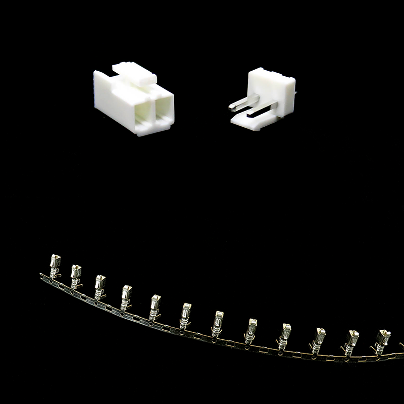
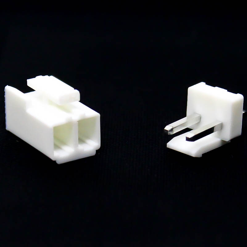
The SPIDER Automation 2-Pin 3.96mm Pitch Male-Female Connector Pair Set is a two-position electrical connector assembly for detachable wiring connections in compatible rechargeable battery packs, radio-controlled equipment, servo systems and battery-balancing arrangements. Its two-contact configuration provides separate electrical paths for a pair of conductors through matching male and female housings. This arrangement is useful for equipment wiring that requires a compact mating interface and convenient disconnection during assembly, servicing or component replacement.
The connector incorporates phosphor bronze contacts with nickel plating and white plastic housings with a UL94V-0 flammability classification. It uses a stated 3.96mm contact pitch and supports a specified wire range of 30–22 AWG. The approximate contact-point pin width is 1.1mm, while the overall connector dimensions are approximately 8 × 8 × 19mm. The stated operating temperature range is −25°C to +85°C. The package contains 10 male-female pairs for compatible wiring and replacement applications.
Product Overview & Two-Contact Configuration
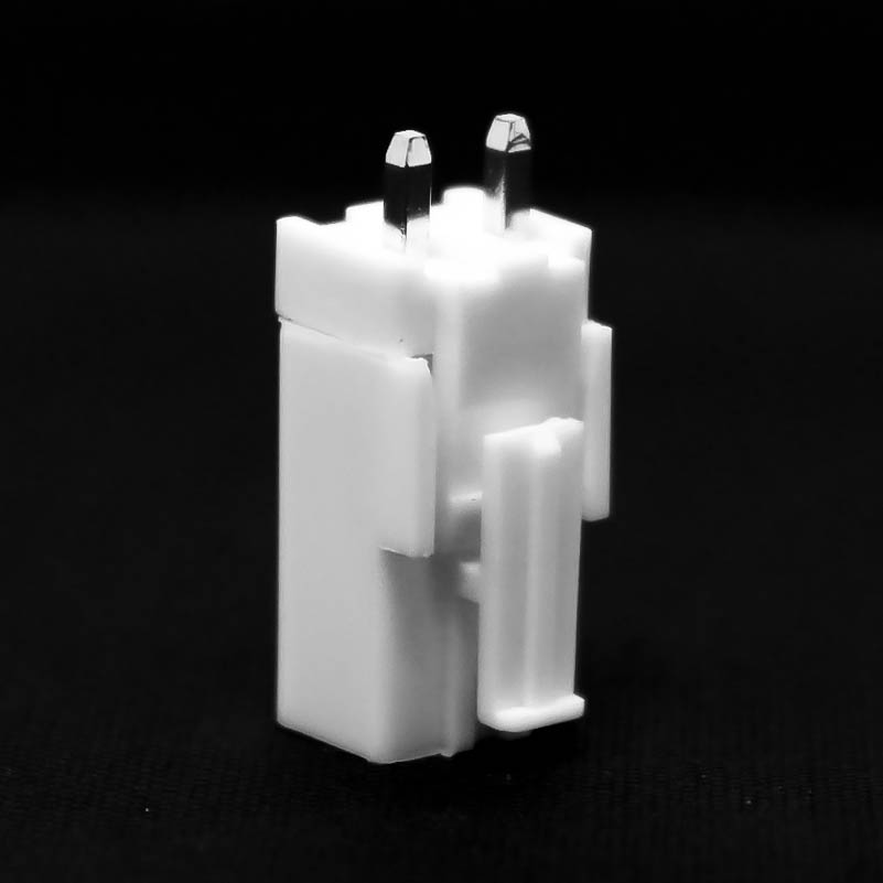
This connector assembly provides two electrical contact positions within a matching male-female housing arrangement. Each contact forms an individual conductive path between the mating connector halves, allowing two conductors to be connected through a single detachable interface.
In a compatible DC power connection, the two conductors may be assigned to positive and negative supply paths. In other equipment, they may carry a pair of application-specific electrical signals. The actual contact assignment depends on the connected equipment’s circuit design and wiring diagram; the connector itself does not define polarity or signal function.
Contact Construction & Plating
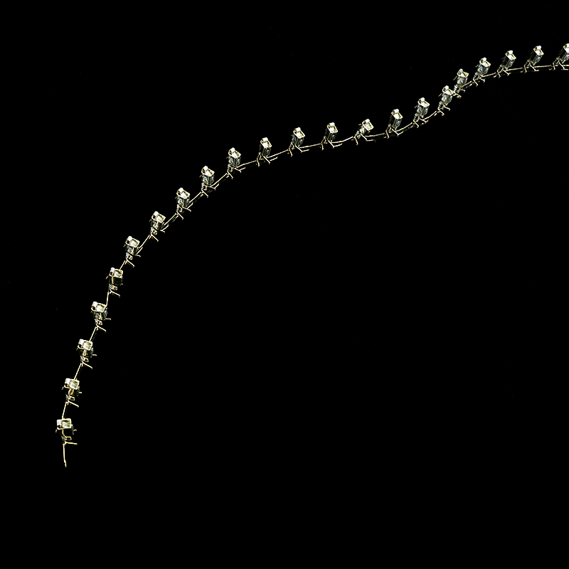
The electrical contacts are manufactured from phosphor bronze with a nickel-plated finish. The contact material provides the conductive elements for the two-position connection, while the nickel plating forms the specified contact surface finish.
The stated contact-point pin width is approximately 1.1mm. Proper mating requires compatible contact geometry, pitch, housing profile and engagement dimensions. A connector with the same number of positions may still be mechanically incompatible if its series or contact arrangement differs.
Wire Compatibility & Housing Design
The specified wire-size range is 30–22 AWG, covering a range of conductor sizes for compatible wiring assemblies. Correct termination depends on matching the conductor size and construction to the actual contact termination method. Suitable wire preparation and secure termination are important for maintaining electrical continuity and mechanical stability.
The connector uses a white plastic housing with a UL94V-0 flammability classification. The housing maintains the two contact positions and supports alignment between the mating connector halves. Its specified operating temperature range is −25°C to +85°C.
Male-Female Pair Configuration
The package contains 10 male-female connector pairs. Each pair provides the corresponding mating halves required to form one detachable two-position connection. This quantity supports multiple compatible wiring assemblies, equipment builds and connector replacement requirements.
Before installation, compare the existing connector’s pitch, contact count, housing dimensions, contact geometry and mating orientation. The 3.96mm pitch and two-position layout should be checked alongside the complete mechanical interface rather than used as the sole compatibility criteria.
Applications
This two-position connector pair set is intended for compatible multi-conductor wiring and detachable electrical connections. Typical application areas include:
- Rechargeable Battery Pack Wiring: Two-conductor connection interfaces in compatible battery assemblies.
- Battery Balancing Equipment: Wiring connections in compatible battery monitoring or balancing arrangements where the equipment uses this connector interface.
- Radio-Controlled Equipment: Power or signal wiring connections in compatible RC electronic assemblies.
- Servo System Connections: Two-conductor connections in compatible servo-related equipment and wiring arrangements.
- DC Power Connections: Detachable two-wire connections in equipment designed around matching connector geometry and electrical ratings.
- Electronic Control Modules: Two-conductor connections between compatible modules and their associated wiring harnesses.
- Custom Cable Harnesses: Assembly of application-specific two-wire harnesses using matching male and female connector halves.
- Equipment Maintenance: Replacement of damaged or worn two-position connector pairs in compatible existing equipment.
- Electronic Assembly Production: Repeated connector installation in compatible equipment manufacturing and wiring operations.
Package Includes
- 2-Pin Male-Female Connector Pair: 10 pairs
Product Specifications
| Parameter | Specification |
|---|---|
| Product Type | Male-female electrical connector pair |
| Connector Configuration | 2-pin / 2-position |
| Contact Pitch | 3.96mm |
| Connector Gender | Male and female pair |
| Number of Contact Positions | 2 |
| Contact Material | Phosphor bronze |
| Contact Plating | Nickel plated |
| Approximate Contact-Point Pin Width | 1.1mm |
| Compatible Wire Size | 30–22 AWG |
| Housing Material | Plastic |
| Flammability Classification | UL94V-0 |
| Operating Temperature | −25°C to +85°C |
| Colour | White |
| Length | 8mm |
| Width | 8mm |
| Height | 19mm |
| Package Configuration | Male-female connector pairs |
| Package Quantity | 10 pairs |
Connection & Operating Recommendations
- Verify Connector Compatibility: Confirm the mating connector has the matching two-position layout, 3.96mm pitch, housing profile and contact geometry.
- Check the Pin Assignment: Identify the function of both contacts from the equipment wiring diagram before connecting the assembly.
- Match Wire Size: Select conductors within the specified 30–22 AWG range and ensure the termination method is suitable for the wire construction.
- Confirm Electrical Ratings: Verify the actual circuit voltage and current requirements against the connector’s confirmed electrical ratings and the capacity of the selected wiring.
- Maintain Correct Polarity: For DC power and battery applications, verify positive and negative connections before mating the connector pair.
- Prepare Conductors Properly: Strip and terminate wires according to the contact design, avoiding damaged strands or loose conductor joints.
- Inspect Contact Condition: Check for bent contacts, contamination or damage before assembly.
- Align Before Mating: Position the two housings correctly and engage them without forcing misaligned contacts.
- Provide Cable Support: Route the wiring to minimise pulling, twisting and repeated bending at the connector entry.
- Test Before Energising: Verify continuity and polarity across the completed wiring assembly before applying power.
- Observe Temperature Limits: Keep the connector within its specified operating temperature range during use.