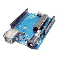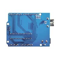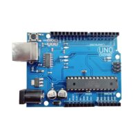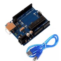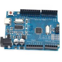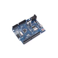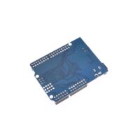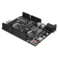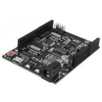

SPIDER Automation | UNO R3 ATmega328P Development Board Kit | USB Cable & Transparent Acrylic Case
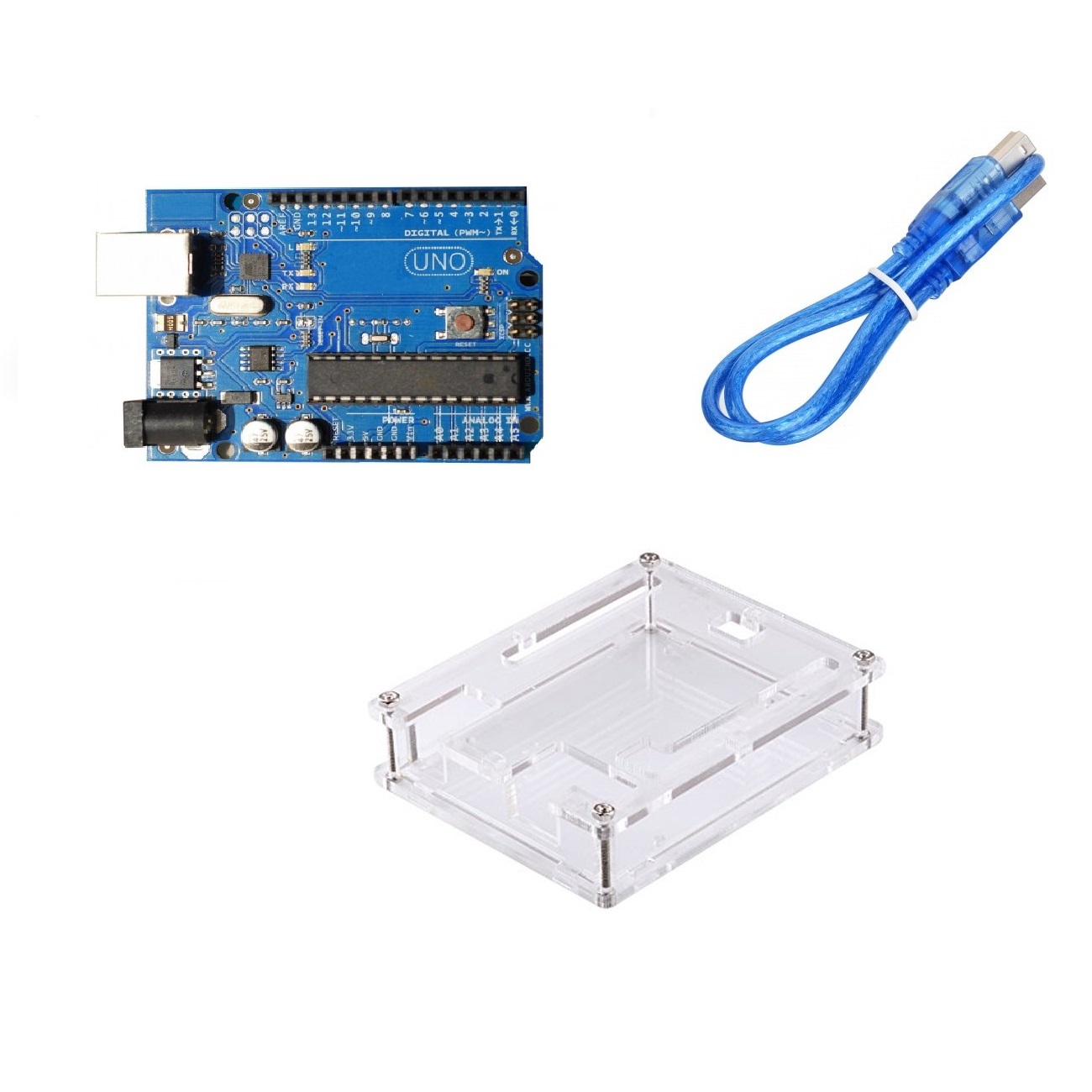
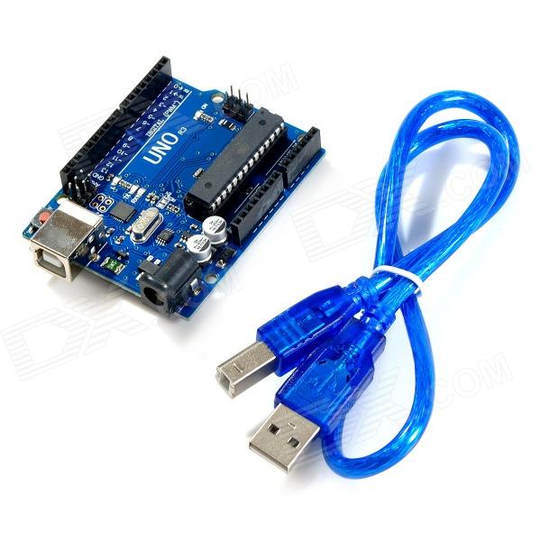
The UNO R3 ATmega328P Development Board Kit is a microcontroller development package combining an UNO R3-compatible board, a USB-A to USB-B cable and a transparent acrylic protective case. The board is based on the ATmega328P 8-bit AVR microcontroller operating at 16MHz and provides 14 digital input/output pins, 6 PWM outputs and 6 analogue input channels. Its standard development-board connection arrangement supports embedded control, sensor interfacing, electronic instrumentation, serial communication and programmable automation prototypes.
The board provides 32KB Flash memory, 2KB SRAM and 1KB EEPROM for firmware storage, runtime processing and non-volatile data retention. It supports USB-based programming and serial communication, as well as UART, SPI and I²C/TWI peripheral interfaces. Power can be supplied through USB or a compatible external DC source, with automatic power-source selection. The included USB cable supports computer connection, while the transparent acrylic case provides a physical enclosure for the development board and helps protect it during handling and integration.
Key Features & Technical Characteristics
- ATmega328P Microcontroller: Uses an 8-bit AVR microcontroller for executing embedded programs and managing connected electronic peripherals.
- 16MHz Operating Clock: Provides the timing reference for firmware execution and microcontroller operations through an onboard ceramic resonator.
- 14 Digital Input/Output Pins: Supports configurable digital input and output connections for external electronic circuits.
- 6 PWM Outputs: Provides 8-bit pulse-width modulation on D3, D5, D6, D9, D10 and D11.
- 6 Analogue Input Channels: A0–A5 support analogue signal measurement with 10-bit resolution, providing 1,024 possible conversion levels.
- UART Serial Communication: Supports TTL-level serial communication through digital pins D0 (RX) and D1 (TX).
- SPI Communication: Supports SPI through D10 (SS), D11 (MOSI), D12 (MISO) and D13 (SCK).
- I²C/TWI Communication: Supports the two-wire interface through A4 (SDA) and A5 (SCL).
- USB Connectivity: Provides a USB connection for computer communication, firmware uploading and USB-powered operation.
- Automatic Power Selection: Supports USB and external DC power inputs with automatic selection between the available sources.
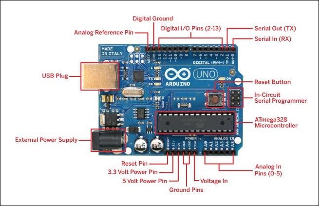
- Power Distribution Connections: Provides VIN, 5V, 3.3V, GND and IOREF connections for compatible circuit integration.
- ICSP Header: Provides access to the in-circuit serial programming connection for compatible programming and development operations.
- Reset Control: Includes a dedicated reset button for restarting the microcontroller during development and testing.
- Transparent Acrylic Enclosure: Provides a visible protective housing for the development board assembly.
- USB Cable Included: Supplied with a USB-A to USB-B cable for connecting the board to a compatible computer.
Microcontroller, Memory & Processing Architecture
The ATmega328P is the central processing component of the UNO R3-compatible development board. Its 16MHz operating clock supports embedded firmware execution, digital signal handling and programmed control operations. The board’s I/O arrangement allows the microcontroller to interface with external sensors, switches, indicators and compatible peripheral circuits.
- 32KB Flash Memory: Stores application firmware and program instructions. A portion is used by the bootloader.
- 2KB SRAM: Provides working memory for variables, temporary data and runtime processing.
- 1KB EEPROM: Supports non-volatile storage of configuration values and other data retained when the board is powered off.
Digital I/O & Analogue Signal Acquisition
The board provides 14 digital input/output pins that can be configured for reading digital signals or controlling compatible external circuits. Six of these pins support 8-bit PWM output: D3, D5, D6, D9, D10 and D11. PWM signals are useful for applications such as LED brightness control, compatible motor-driver inputs and other duty-cycle-controlled interfaces.
The six analogue inputs, labelled A0 through A5, use the microcontroller’s 10-bit analogue-to-digital converter. This provides 1,024 discrete conversion levels for measuring compatible analogue voltage signals. The default measurement reference is associated with the board’s 5V supply, while the AREF connection supports an externally configured analogue reference when used with the appropriate firmware configuration.
Communication Interfaces
The UNO R3 connection layout supports several communication methods for interfacing with computers, microcontrollers and external electronic modules.
- UART / TTL Serial: Digital pin D0 (RX) receives serial data, while D1 (TX) transmits serial data. These pins support communication with compatible TTL-level serial devices.
- SPI: The SPI interface uses D10 (SS), D11 (MOSI), D12 (MISO) and D13 (SCK) for communication with compatible SPI peripherals.
- I²C / TWI: The two-wire interface uses A4 (SDA) and A5 (SCL) to communicate with compatible sensors, controllers and peripheral modules.
- USB Serial Communication: The USB connection provides computer communication and a serial interface for supported development workflows.
- Software-Based Serial: Compatible firmware can implement additional serial communication through supported digital pins using a software serial implementation.
Power Supply & Distribution
The development board supports power through its USB connection or an external DC supply. External power can be connected through the onboard DC power jack or the VIN and GND connections. The power-selection circuit automatically selects between the available power sources.
The recommended external input range is 7–12V DC. Although the board can accept a wider external input range of 6–20V, operation near the lower or upper limits may affect stability and regulator temperature. The 3.3V output is generated by the onboard regulator and supports a maximum current draw of 50mA.
Power Connections
- VIN: External input voltage connection when powering the board through the VIN pin. It also provides access to the external input supplied through the DC power jack.
- 5V: Regulated 5V power rail for compatible peripherals and circuits. Applying an external supply directly to this pin bypasses the onboard regulator and power-selection protection.
- 3.3V: Regulated 3.3V output generated by the onboard regulator, with a maximum current draw of 50mA.
- GND: Common ground connections for the board and compatible external circuits.
- IOREF: Provides the board’s operating logic-voltage reference for compatible expansion hardware.
Transparent Acrylic Protective Case
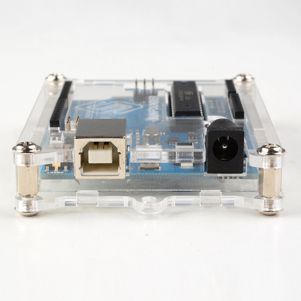
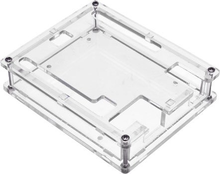
The included transparent acrylic case provides a physical enclosure for the UNO R3-compatible development board. Its transparent construction keeps the board visible while providing a protective housing for routine handling, bench development and installation in suitable electronic assemblies.
The enclosure is intended to be used with the supplied development board. During assembly, align the case components and board mounting points carefully, ensuring that the USB connector, power jack, reset button and required connection headers remain accessible. The enclosure should not obstruct ventilation or place mechanical stress on the board connectors.
Applications
The UNO R3 board’s digital and analogue I/O resources, communication interfaces and compact protective enclosure make this kit suitable for a range of embedded engineering and electronics development applications.
- Embedded Control Systems: Development of microcontroller-based control units for electronic equipment and automated assemblies.
- Sensor Monitoring: Acquisition of analogue and digital signals from compatible environmental, position and measurement sensors.
- Robotics Control: Interfacing sensors, indicators and external motor-driver circuits in robotic control platforms.
- Motor Driver Interfaces: Generation of PWM control signals for compatible DC motor and actuator driver circuits.
- Industrial Automation Prototypes: Evaluation of input/output control logic and peripheral integration for automation systems.
- Data Acquisition: Reading analogue voltage signals and digital status inputs for monitoring and measurement applications.
- Serial Communication Systems: Integration with compatible UART, SPI and I²C/TWI communication peripherals.
- Instrumentation & Measurement: Development of electronic measurement interfaces using analogue inputs and external signal-conditioning circuits.
- USB-Connected Electronics: Development and testing of microcontroller-based devices that communicate with a host computer over USB.
- Control Panel Prototypes: Integration of switches, status indicators and external control interfaces.
- Embedded Firmware Development: Testing program logic, peripheral functions and I/O assignments before dedicated PCB development.
- Engineering Training & Laboratory Work: Structured development of microcontroller programming, digital electronics and embedded-system concepts.
Package Includes
- 1 × UNO R3-Compatible ATmega328P Development Board
- 1 × USB-A to USB-B Cable
- 1 × Transparent Acrylic Protective Case
Product Specifications
| Parameter | Specification |
|---|---|
| Product Type | Microcontroller Development Board Kit |
| Board Compatibility | UNO R3-Compatible |
| Microcontroller | ATmega328P |
| Architecture | 8-bit AVR |
| Clock Speed | 16MHz |
| Operating Voltage | 5V DC |
| Recommended External Input Voltage | 7–12V DC |
| External Input Range | 6–20V DC |
| Digital I/O Pins | 14 |
| PWM Output Pins | 6 (D3, D5, D6, D9, D10, D11) |
| Analogue Input Pins | 6 (A0–A5) |
| Analogue Resolution | 10-bit (1,024 levels) |
| Flash Memory | 32KB (0.5KB used by bootloader) |
| SRAM | 2KB |
| EEPROM | 1KB |
| UART Serial Pins | D0 (RX), D1 (TX) |
| SPI Pins | D10 (SS), D11 (MOSI), D12 (MISO), D13 (SCK) |
| I²C/TWI Pins | A4 (SDA), A5 (SCL) |
| 3.3V Output | 3.3V DC, maximum 50mA |
| Digital I/O Logic Voltage | 5V |
| Digital I/O Maximum Current | 40mA per pin (absolute maximum rating, not a recommended continuous operating current) |
| Power Input Options | USB or external DC supply through power jack / VIN |
| Power Selection | Automatic |
| USB Cable | USB-A to USB-B |
| Enclosure | Transparent acrylic case |
Connection & Operating Recommendations
- USB Connection: Connect the supplied USB-A to USB-B cable between the board and a compatible computer for programming, serial communication or USB-powered operation.
- External Power Supply: For external DC operation, use a compatible 7–12V supply through the power jack or VIN connection. A regulated adapter within this range is suitable for typical development use.
- Power Input Polarity: When using the DC power jack, use a compatible 2.1mm centre-positive plug. Verify polarity before connecting any external supply through the VIN and GND headers.
- Regulated Power Pins: Use the 5V and 3.3V pins as regulated outputs for compatible low-power peripherals. Avoid applying an external supply directly to these pins unless the board’s power architecture and required protection arrangements are specifically understood.
- Peripheral Voltage Matching: Confirm that connected modules and sensors are compatible with the board’s 5V logic. Use appropriate level-shifting circuits when interfacing with lower-voltage logic devices.
- Analogue Signal Connection: Keep analogue input signals within the permitted measurement range and configure the reference voltage appropriately when using AREF.
- Digital I/O Protection: Keep pin currents within the microcontroller’s electrical limits. The 40mA per-pin figure is an absolute maximum, not a recommended continuous load current.
- Motor & Actuator Interfaces: Use appropriately rated driver circuits for motors, relays, solenoids and other inductive or higher-current loads. Do not connect these loads directly to the microcontroller I/O pins.
- Communication Wiring: Follow the correct UART, SPI and I²C/TWI pin assignments and ensure that connected devices share a suitable ground reference.
- Acrylic Case Assembly: Align the enclosure components with the board mounting points and keep the USB connector, DC jack, reset button and required headers accessible.
- Enclosure Ventilation: Avoid enclosing the board in a way that traps excessive heat around the voltage regulator or other powered components.
- Development Environment: Select the correct UNO R3-compatible board configuration and communication port before compiling and uploading firmware.