
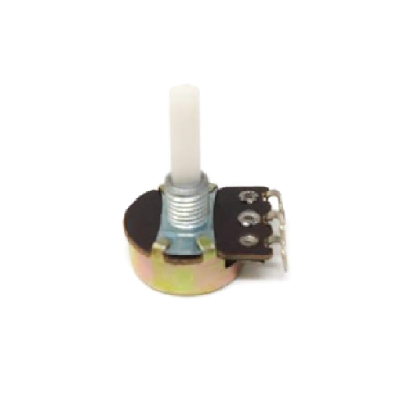

SPIDER Automation | 1kΩ 3-Pin Rotary Potentiometer with 15mm Shaft & Knob | Manual Analogue Control
The 1kΩ 3-Pin Rotary Potentiometer is a manually adjustable resistive component used for setting voltage levels, adjusting analogue signals and providing rotary control in electronic circuits. Its three-terminal arrangement consists of the two ends of a resistive element and a movable wiper, allowing it to function as an adjustable voltage divider or as a variable resistor according to the circuit design. The 1kΩ nominal resistance makes it suitable for applications specifically designed around this resistance value.
Each unit features a 15mm shaft with a supplied plastic control knob for convenient manual operation. This arrangement supports integration into electronic equipment and control assemblies where users need direct access to a rotary adjustment. Supplied as a pack of three, the set includes three potentiometers and three matching knobs for multiple control positions, equipment servicing or electronic assembly requirements.
Product Overview & Functional Design
A rotary potentiometer changes the electrical relationship between its terminals as the shaft is rotated. The internal wiper moves along the resistive element, varying the resistance between the wiper and either end terminal. When connected across a reference voltage, the wiper can provide an adjustable output voltage; when connected using the wiper and one end terminal, it can provide a variable resistance.
The supplied plastic knob provides a practical grip for turning the shaft and operating the control. This makes the component suitable for equipment interfaces where a physical rotary adjustment is preferred over an onboard preset trimmer or software-controlled setting.
Technical Features & Functional Characteristics
- 1kΩ Resistance: Provides a nominal total resistance of 1,000 ohms across the two ends of the resistive element.
- Three-Terminal Design: Provides two fixed resistive-element terminals and one movable wiper terminal.
- Rotary Operation: Changes the wiper position through shaft rotation to provide manual resistance or voltage adjustment.
- 15mm Shaft: Provides the mechanical interface for fitting and operating the supplied control knob.
- Plastic Knob: Provides a user-operated grip for rotary adjustment.
- Voltage-Divider Operation: Can provide an adjustable wiper voltage when connected across a suitable reference supply.
- Variable-Resistance Operation: Can be connected between the wiper and one end terminal to provide adjustable resistance.
- Three-Unit Supply: Includes three potentiometers and three knobs for multiple control locations or replacement applications.
Electrical Configuration & Connection
The three terminals support two common potentiometer connection methods:
- Voltage-Divider Connection: Connect the two outer terminals across the circuit’s reference voltage and ground. The centre wiper terminal provides an adjustable voltage output as the shaft is rotated.
- Variable-Resistance Connection: Use the wiper terminal and one outer terminal to obtain an adjustable resistance. Select the appropriate outer terminal according to the required direction of resistance change.
Confirm the terminal arrangement and intended circuit function before wiring. The potentiometer’s resistance value alone does not establish its permissible operating voltage, power dissipation or suitability for directly carrying a motor or other high-current load.
Mechanical Design & Installation
- Shaft-and-Knob Operation: The 15mm shaft accepts the supplied plastic knob for convenient manual adjustment.
- Control Access: Position the potentiometer so the shaft remains accessible from the intended equipment or panel operating surface.
- Mounting Arrangement: Select a mounting method and panel or PCB layout compatible with the actual body, terminals and shaft geometry.
- Knob Fitment: Align the knob with the shaft and secure it without applying excessive force.
Applications
This 1kΩ rotary potentiometer can be incorporated into electronic assemblies that require a manually adjustable resistance or analogue control input, provided the circuit is designed for its electrical rating and mechanical configuration.
- Audio Signal Adjustment: Providing manual level adjustment in compatible audio circuits designed for a 1kΩ potentiometer.
- Analogue Voltage Setting: Generating an adjustable voltage-divider output for suitable analogue input or reference circuits.
- LED Brightness Control: Adjusting a control voltage or reference input in compatible LED driver circuits.
- Motor Speed Reference: Setting an analogue speed command for motor controllers that accept a potentiometer-based control input.
- Signal-Level Adjustment: Providing manual adjustment in analogue signal-conditioning and interface circuits.
- Instrumentation Controls: Supporting user-operated adjustment functions in compatible laboratory and measurement equipment.
- Embedded Controller Interfaces: Providing a variable analogue input to microcontroller-based systems when connected to a suitable input circuit.
- Industrial Control Panels: Serving as a manual rotary adjustment component in control assemblies designed around its 1kΩ value.
- Electronic Equipment Servicing: Replacing compatible rotary potentiometers in equipment maintenance and repair.
- Electronic Assembly: Providing rotary adjustment components for control interfaces and analogue circuit assemblies.
Package Includes
- 3 × 1kΩ 3-Pin 15mm Shaft Rotary Potentiometers
- 3 × Plastic Control Knobs
Product Specifications
| Parameter | Specification |
|---|---|
| Component Type | Rotary Potentiometer |
| Nominal Resistance | 1kΩ |
| Terminal Configuration | 3-Pin |
| Control Type | Rotary Manual Adjustment |
| Shaft Length | 15mm |
| Knob Material | Plastic |
| Knob Included | Yes |
| Package Quantity | 3 Potentiometers |
| Knob Quantity | 3 Plastic Knobs |
Installation & Operating Recommendations
- Resistance Selection: Confirm that the circuit is designed for a 1kΩ potentiometer before installation. The resistance value affects the current drawn by the connected divider or resistive network.
- Terminal Identification: Identify the two outer resistive-element terminals and the centre wiper terminal before making connections. Verify the actual terminal layout against the component configuration.
- Supply and Signal Limits: Keep the applied voltage, current and power dissipation within the component’s rated operating limits. Do not connect the potentiometer directly to a load whose current exceeds its capability.
- Panel or PCB Fitment: Check the component body, shaft clearance and mounting arrangement against the intended enclosure or board layout before installation.
- Knob Installation: Fit the plastic knob squarely onto the shaft and avoid excessive pressure that could damage the shaft or internal mechanism.
- Adjustment Procedure: Rotate the knob gradually while monitoring the relevant circuit voltage, signal or operating response to reach the desired setting.
- Embedded-System Interface: When using the wiper as a microcontroller analogue input, ensure the output voltage remains within the controller’s input-voltage limits and provide suitable signal conditioning where required.
- Final Testing: Verify the resistance variation and circuit response throughout the required adjustment range before placing the equipment into service.


